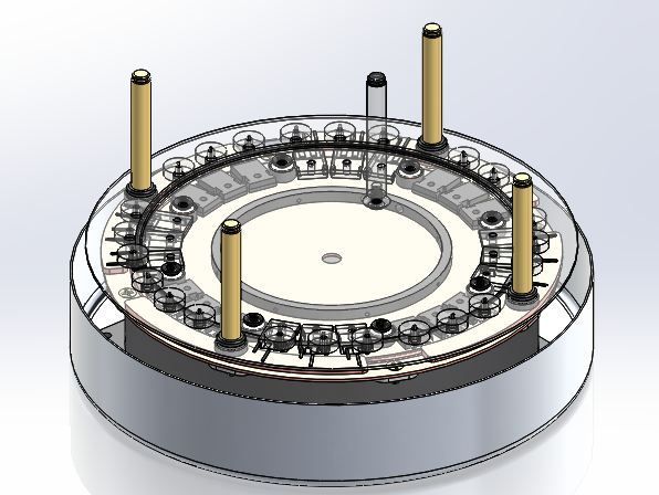
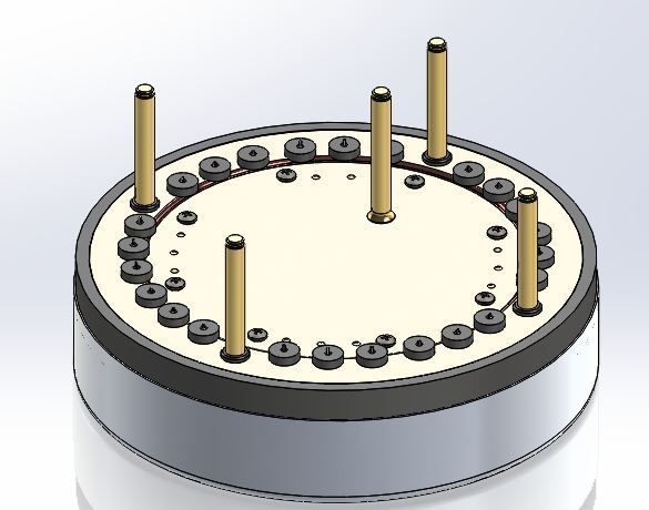
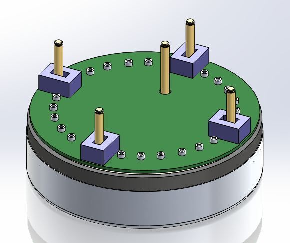
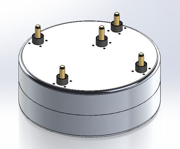
So here are a few more views of the compact inverter.
This design is very compact and pretty light. The dry weight at this point is 6.35kg. Its volume is 6.1 L, not including the output pins. Its main case is 104mm tall and 272mm in diameter. These specs are a bit smaller/lighter than the OE Toyota specs.

Of course the power/weight numbers depend heavily on how many switches are used and how hard they are driven.
The main foundation is like the previous pic I posted. I've been working out issues like sealing out the coolant, fastening stuff, and packaging things as small as reasonable.
The current sensor problem worked out pretty well. You can use the standard LEM current sensors with a couple small mods: - Cut the bolt flange off and cut off the little plastic guide around the connection pins. Note also that everything is on one controller board. There is no need for any extra connections. Temperature sensing would be easy and accurate by just putting a thermistor on the bus pan.
The input/output pins are 10mm radlock pins. These are very reliable, high current density parts - the 10mm pin can handle 300A. I've also used the 3.6mm radsock connector for the gate connection. Again, these are very high reliability parts with a helical contact to the pin. They can handle WAY more current than is necessary to drive the switch. Another option would be to directly solder the gate legs to the circuit board. Of course that would make disassembly nearly impossible.
I've shown in the drawings a design that uses all the parts that could possibly fit. Of course they can be left off in reality - for example, there are four current sensors shown - one for the input booster and one for each phase.
It would also be easy to skip the boost converter part. The input high side would just connect directly to the lower bus plate. It would give room for more switches, so the inverter could be capable of a higher output.
So, with a boost converter, it's possibe to fit 6 switches per phase - or 3 high, 3 low.
Without a boost converter, it's possible to fit 8 switches per phase. At this point, it would be limited to the output pin capability of 300A. Of course the larger pin could be used, but at this point we're looking at about 195kW with a 650V input.
I'm still working out the cooling details, but generally it's using a cooling oil that circulates around the capacitor and between the plates. The switch legs are immersed in flowing coolant, as are the output bus bars. Hot spots on the legs, switches etc. should not be an issue.

Controller with the top cover, removed and the low side plate transparent:

Here is the insulator/seal shown with the low side plate visible.

Here is the circuit board: Note the modded current sensors and the connectors for the gate pins:

Here is a nearly complete inverter. It still needs connectors for the controller and coolant connections.

- E*clipse