Here's a quick work-in progress of the round controller:
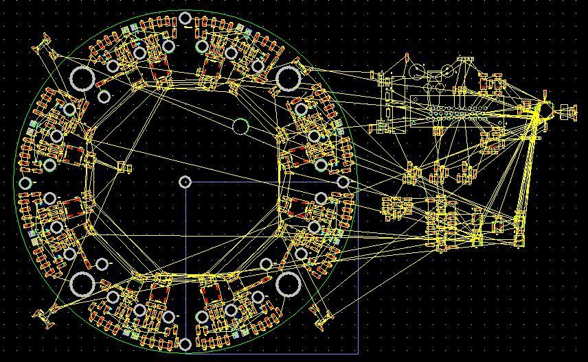
Obviously it's not complete, but it looks like it will be possible to fit everything within the 265mm 2 layer circuit board restriction. I still have to see whether I can actually do this with only 2 layers, but there is a good possibility.
The four large holes are the output pin/current sensor holes. They also double as the connectors for the high side switches' emmitters and the low side switches' collectors.
On either side of the output holes are separate drivers for each set of three mostfet/IGBT/SiC switches. It's basically the same as Paul's original design with surface mount parts. While it has been VERY TEMPTING to use smaller parts, I've restricted parts to be SOIC and about 1206 minimum. While there are a lot of parts, they will be hand-placeable.

In the center is (I think) barely enough space to fit the control stuff and one big connector. Dang that connector takes a lot of board space...

So far the design includes all the stuff the original design includes, especially all the safety override circuits.
24V power supply input
Relay controls for the precharge relay and main contactor
2 CAN busses and the drivers for them
2 RS232 serial busses - standard and Rasp. Pi.
4 current sensors, 1 for each output and 1 for a boost controller
Quadrature encoder interface OR resolver input + motor temp sensor
Temperature sensor
3 independant throttle inputs - why 3?? OE throttles have 2 inputs, to make sure they are working correctly. Also, if one wants to do some form of throttle override using an external microprocessor or a proportional regen braking setup - use the 3rd throttle.
Regarding the throttle, I made the circuit work for 3 wire pots or hall effect sensors that are driven by +5V. I've ditched the 2 wire throttle sensor to keeps things reasonably straight forward.
So far, the I/O listed above has been accounted for in the output connector. There are a few spaces left.
That said, I think using two big connectors to make more pins available will be tough, at best. So, I think it might be smart to consider sharing common pins - Control Ground and +5V would be good candidates since they need to pass very little current. It might be smart to separate the analog input stuff from the digital I/O stuff.
Thoughts? Suggestions? Questions?
- E*clipse