Quote:
Originally Posted by e*clipse

The number is a bit lower than the TI app note's maximum switch current of 202A, but two completely different methods produced close results. 
- E*clipse |
I was forgetting about efficiency. If their current was 202amp, and assuming 100% efficient the input current was 160, I bet the higher current came from the boost losses as well as inverter losses.
Thingstodo, sorry the 3x current boost question was to p-hack. But I just threw it right in as if it was responding to you.
You know, there is also an inductor from them that is 100 amp continuous and is 120uH. That's only 8 pounds and is $128 ($110 in quantity 10). I know the 200amp version was rated for up to 300amp intermittent without the inductance being impacted much (it was not close to saturating at that current). I can't find the stupid graph they sent me now though. I bet the 100amp could do 150amp for short periods.
Here are 3 graphs for what the boosting looks like. The battery amps are blue. The switch is green. Some of it is hidden by the blue. The red is the DC "capacitor current" that is being fed to the inverter.
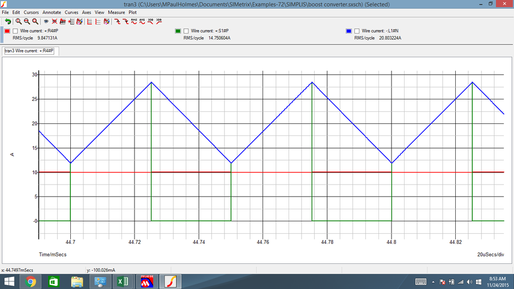
So, from the graph, switch RMS current is around:
Code:
IswitchRMS = (Ibatt + Icaps) / 2
IswitchRMS = (3*IphasePeak + 1.5*IphasePeak)/2
IswitchRMS = 2.25*IphasePeak
IswitchRMS = 3.18*IphaseRMS
And again from the graph,
Code:
IswitchPEAK = 2.8*Icaps
IswitchPEAK = 2.8 * 1.5 * IphasePeak = 4.2 * IphasePeak
IswitchPeak = 4.2 * sqrt(2) * IphaseRMS = 6 * IphaseRMS