Quote:
Originally Posted by freebeard

So any discontinuity in the approach or the edge will cause the uniform ring to slough sideways and feed an unwanted vortex?
The search term for 'jet pumping action' would be 'box cavity'?
I'm curious about what you refer to. Perforated base plate?
|
*On a streamline body,the velocity and pressure measured transversley,anywhere along the body is the same.
*On a streamline half-body,in ground proximity,this condition can also be the same if particular attention is paid to the underbody.
*Hucho emphasizes that bodies generate only gentle pressure gradients along the body pathway,with no 'kinks.'
*If the truncation is not perfectly transverse,the entire base pressure of the wake will be determined by the first point of separation and it's associated static pressure.
*There is essentially zero static pressure near the windshield,it's all been converted to velocity pressure.
*The most forward point of separation has the lowest pressure,and all the air will attempt to flow towards this location,shearing the flow up into eddies,vortices,then full-blown turbulence.
*So we want gentle contours,then a sharp cut off
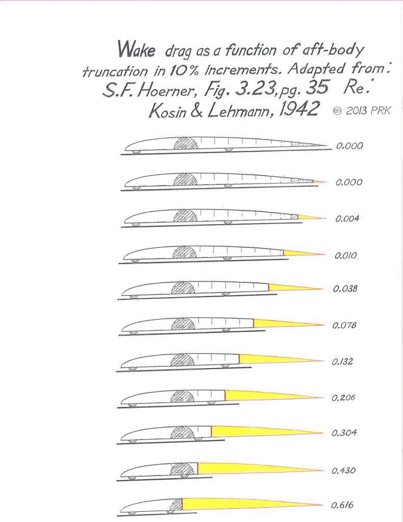
This is what Kamm/Koenig-Fachsenfeld advocated so strongly
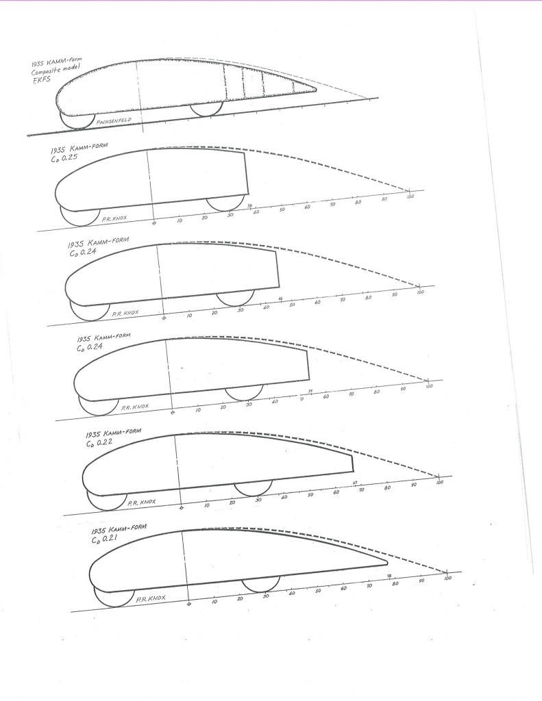
Here, Renault has done it with their Vesta II concept
Here,Daihatsu uses it with their UFE-II
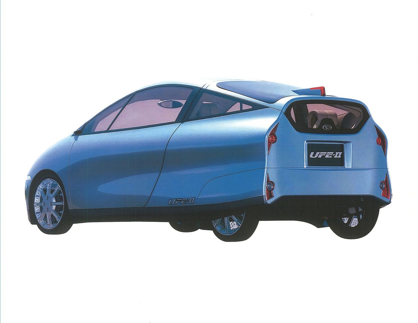
But only Morelli provides the elliptical rear transom which is capable of generating the 'fluid' tail
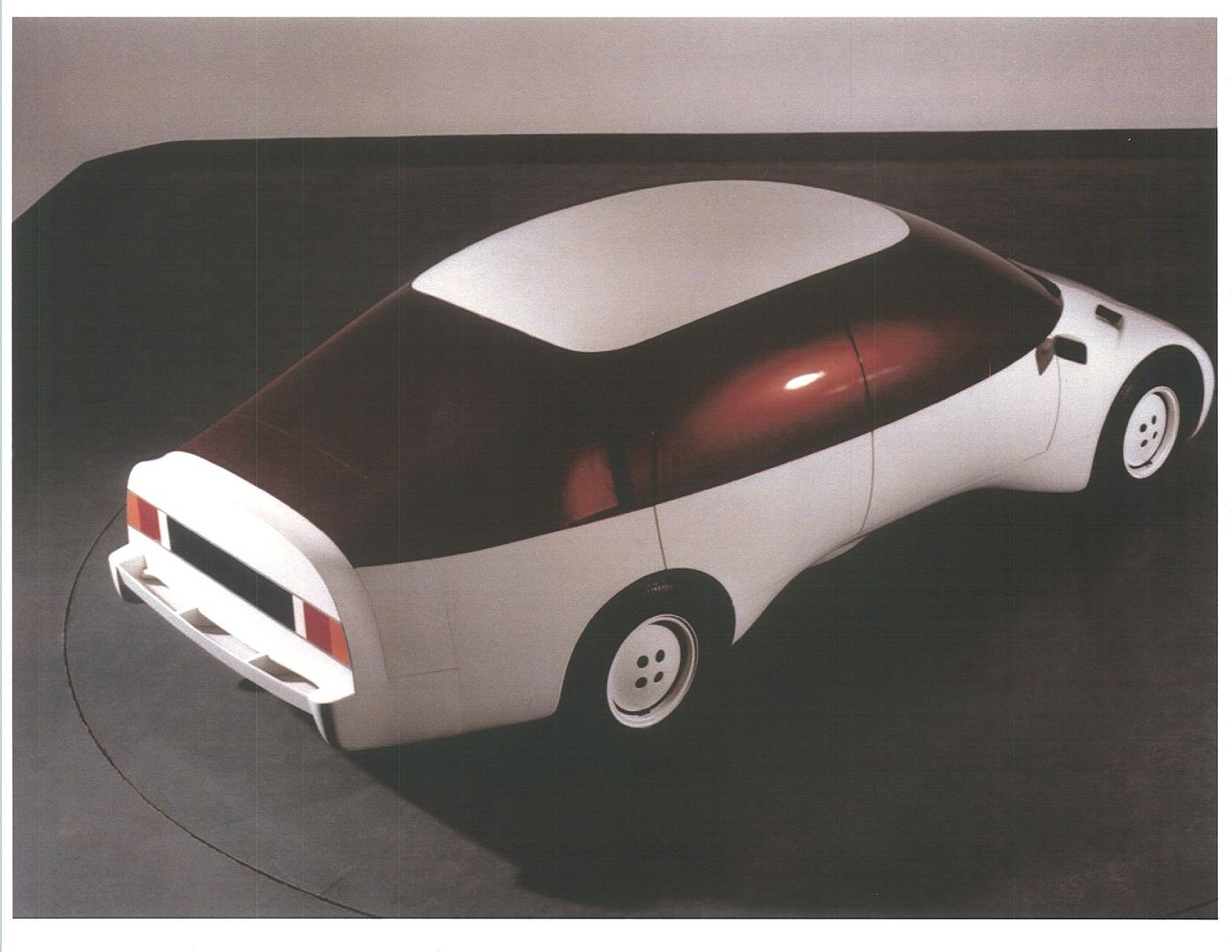
.
--------------------------------------------------------------------------
The jet pumping action is covered in Sighard Hoerner's book,AERODYNAMIC DRAG,from 1951,in the section on boat-tailed projectiles in free flight.The air attempts to pump air into the 'buttock' (as Lanchester referred to the )void behind the bullet or fuselage machine-gun turret.As the air curves around and impacts the transom,it imparts some forward momentum.Morelli depicts a similar phenomena with the fluid tail technique (FTT).Dornier aircraft works also experienced this phenomena with respect to truncated wing trailing edges that they studied leading up to their 1920 patented wing.
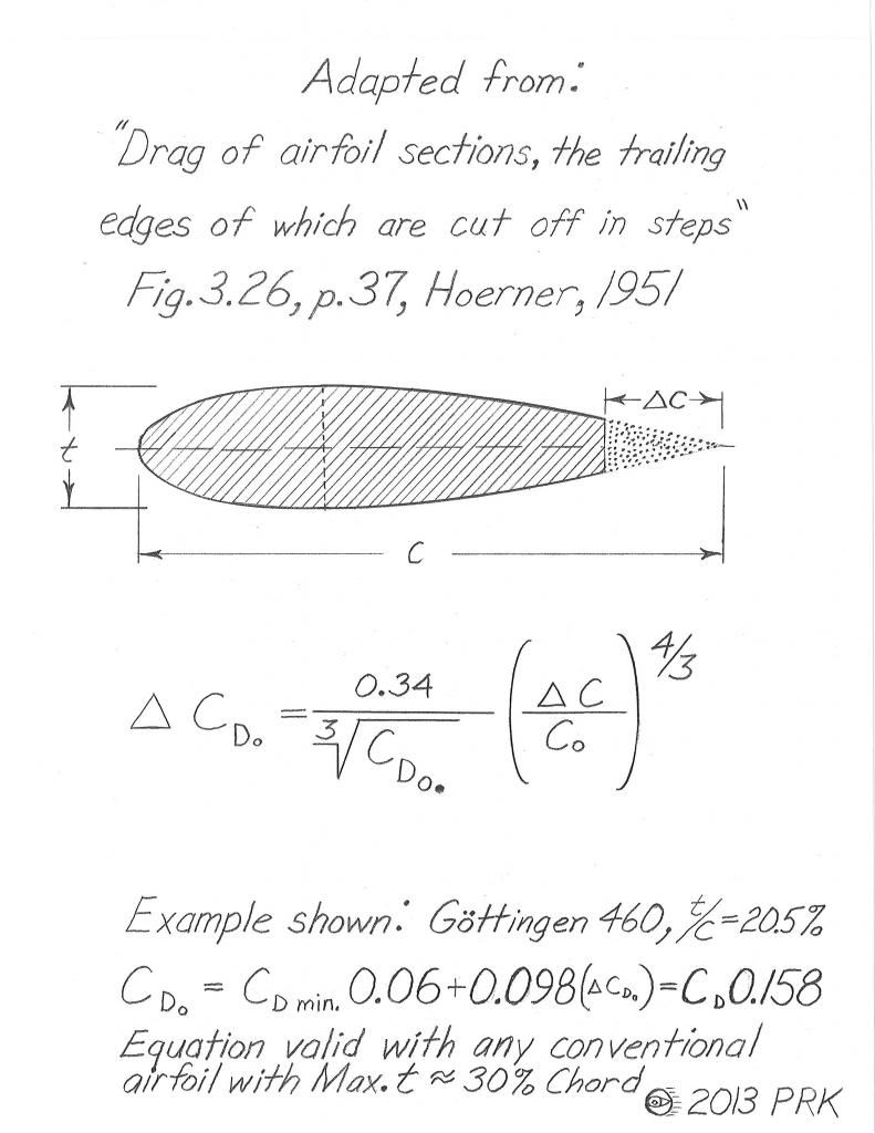
Here is the equation for calculating the drag increase of any degree of wing truncation.5% is considered the maximum that can be removed before a significant drag increase is seen
