Slow Progress but still progress.
The coupler between the electric motor and the gearbox has been completed.
Here is a picture of the parts.
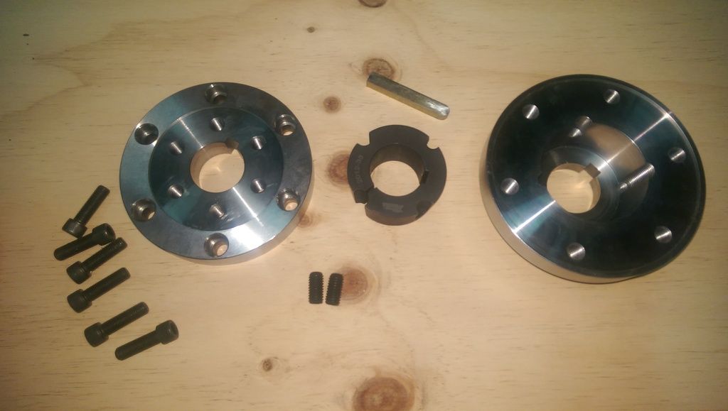
I am retaining the clutch and flywheel so this adaptor is just to attach the flywheel to the motor shaft. Previously the flywheel connected to the end of the crankshaft on the ICE engine.
The adaptor has three parts. A keyed back plate that has the tapered void to house the taper lock. (rightmost in image) Then there is the taper lock itself, also keyed. (center of image) Then there is the front plate. (leftmost in image) The front plate is also keyed. The front plate is used to adapt the bolt placement on the flywheel which has a small distance from center to the larger distance from center bolt spacing of the back plate. The large distance from center is required on the back plate due to the large diameter of the taper lock.
This is not the final assembly picture, just a dry fit to see if there are any issues.
Back plate in place on the motor output shaft.
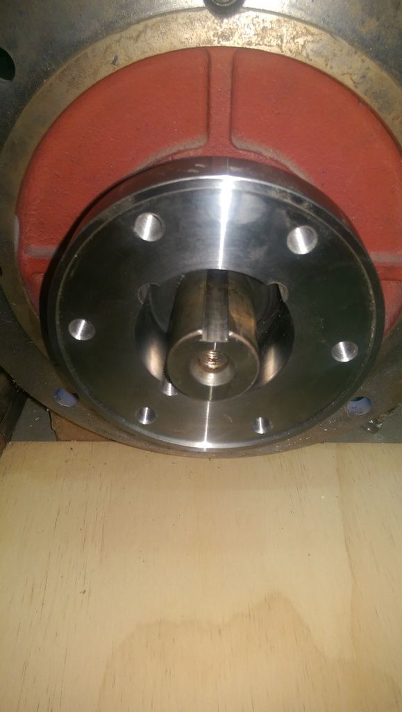
Next the taper lock.
The taper lock constricts as it is pulled down into the back plate by grub screws.
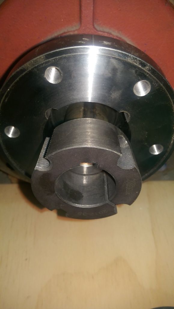
Here is a view of the parts off of the shaft so it is easier to see. The taper lock is pulled down into into the back plate. You can also see the key that runs through all three pieces of the adaptor.
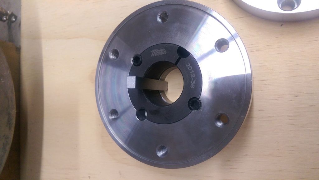
Then the front plate is attached using 6 recessed hex head bolts.
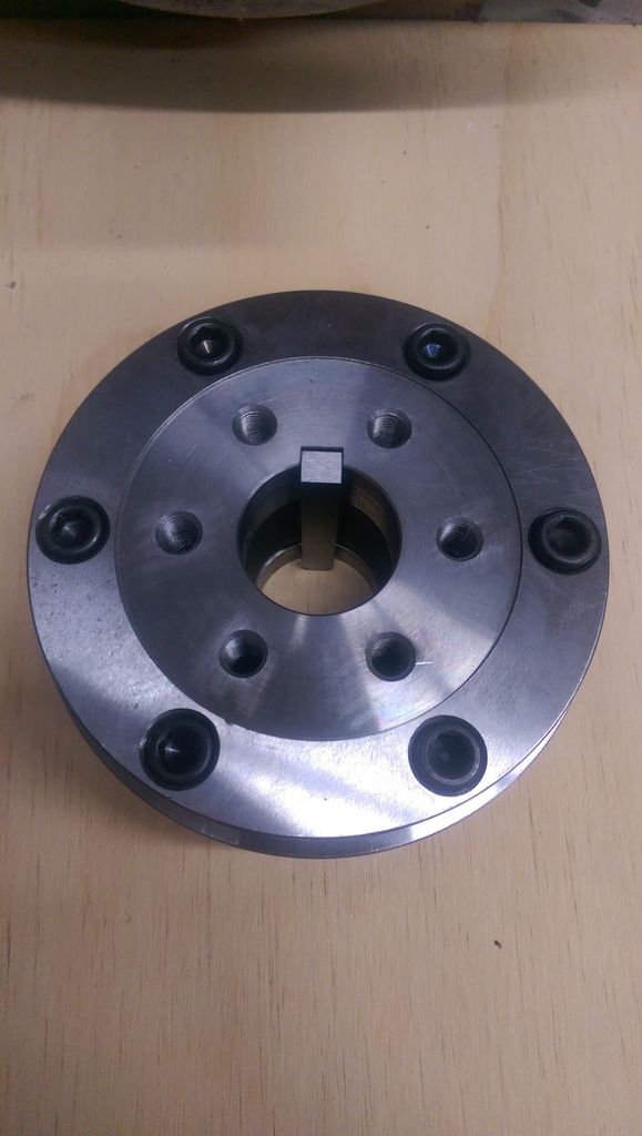
The front plate has 6 threaded bolt holes that match the spacing on the flywheel. The flywheel attaches to the front plate using the same bolts that previously attached it to the crankshaft.
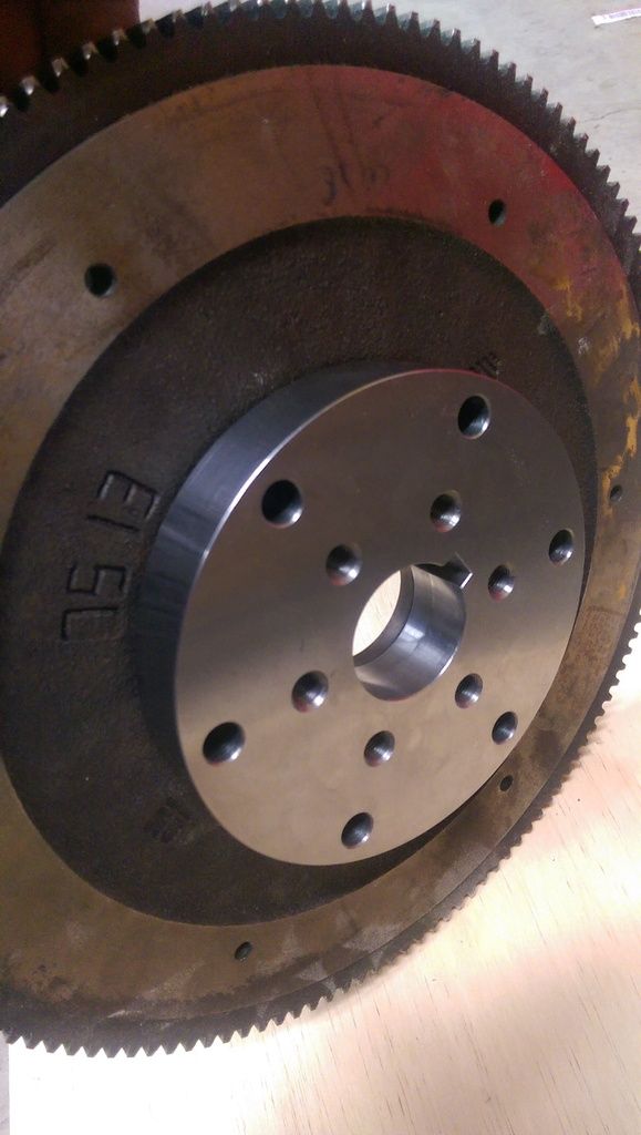
So the flywheel is held by a key through all three parts as well as a large taper lock.
I don't foresee any slippage.

Now that the shaft to flywheel adaptor is built we can look at making the adaptor plate that will connect the motor casing to the gearbox casing. With the flywheel attached to the motor we now know how thick to mill the adaptor plate so that the flywheel ends up in the same position it was in with the ICE engine.
Then once that is done and the gearbox and motor are joined we can create the engine mount to suit the motors final position.