During my lunchbreak today, i made an electrical shedule to help me wire all the correct wiring.
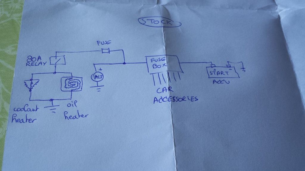
This is the stock car electrical system:
(note the added oil and coolant heater)

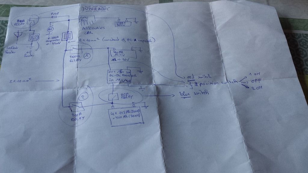
And this is how it will look like when it is done:
(The 4 deep cycle batteries will be grid charged and should have
hopefully enough capacity to get me 4 days to work = 8 times 45 minutes = 6 houres of run time)

The heaters now are working like this:
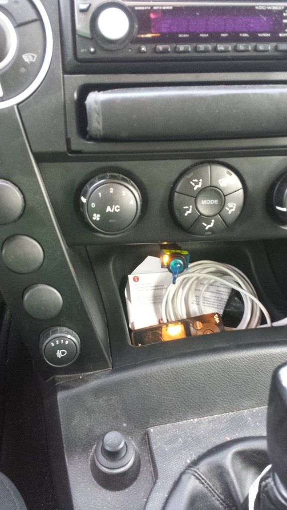
The blue switch is for the coolant heater that is powerd by an 80A relay.
The red switch is for the heater pad that is pasted to the underside of the oil carter.
I only have this photo, but now there is at the right of the blue switch an identical red switch
 What will be different?
1
 The oil heater wil be activated also powerd by the 80A relay (i always use both heaters, never one or the other).
So the red switch comes free. (or the blue one)
2 This unused switch wil then activate the relay so the DC tot DC converter charges the 14,4V buffer battery. I call this the high voltage feed (exlpained further down this post)
3 The 3th switch is an 3 position switch.
-Position one is to use the high voltage feed.
-Position two is when the car is parcked, no connection from the additional batteries to the car.
-Position three is when the high voltage feed fails and is a direct connection of the 12V bank to the car. (or when cranking if it is freezing cold)
The high voltage feed explained:
It needs to charge the starting batterie and keep the lights working at full brightness, i want a 13,5V to 14,8V feed.
Because the DC to DC converter has limited capacity, i placed a battery that can handle the higher voltage as a buffer. (empty voltage of 12V (safe zone) and full voltage of 16,8V (wont be charged or disscharged to those levels, so lifetime will be long enough).
The DC to DC converter explained:
This converter exist out of 4 converters.
Maximum current in rating is 10A.
I will limit everey converter to use only 7A as input.
Together they will draw 28 to 30Amps out of the bank.
With an efficiency of 80%. It probably puts out 18,5Amps at 15,5V.
If it draws more amps, then i need to ad an electric fan to cool those.
Time will tell how much the car uses and how much i can get safely out of the converter.
If all fails, i use the backup to run directly of the 12V bank.
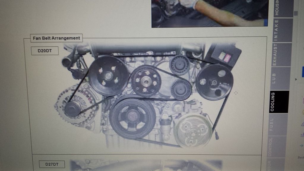
The first step is do disconnect the activate wire of the alternator (already found that wire).
When i get a long enough autonomie.
I will calculate and messure how long the shorter serpentine belt needs to be to not run the alternator.
(It is easy done, cause the belt contact the wheel on the upper side AND lower side, so it only needs to ga around this wheel and forget about the alternator)
