Hey guys, this is a development thread, I finally got it working on page 4. I now have a finished product, which is a small arduino pcb clone programmed to generate the wave used in conjunction with a spdt switch. If you have an Insight and would like one, they are for sale, send me a pm here or on Insight Central. There is a thread in buy-and-sell on IC where availability info and prices can be found, but I will respond to private messages here also.
################
Background Info:
So some guy on IC tried to make a chip that would trick the car into thinking conditions were 'right' for auto stop, and it would let you AS basically on command. (This is NOT suitable for CVT, only for 5MT.) I've been trying to duplicate his work, he rolled his Insight a couple years ago.

For AS in the manual the car wants:
- Neutral
- Low Speed (< 19MPH + deceleration)
- Outside temp above 32°F
- Engine sorta warm (I think about 120°F+ going by my ScanGauge)
- IMA not too low (no bg charge)
IMA, engine temp, and shifter in neutral are all things you probably want to be required before you auto-stop, but OAT and speed are things we don't really want as a factor. That's where EFAS comes in.
The main component is a switch where if you press it then the VSS signal going to the ECM is replaced with a spammed signal from a 555 Timer of a square wave of about 2HZ, to make the car think it's going like 1mph. An optional secondary component is for, when the switch is pressed, the OAT sensor gets a47k ohm resistor wired into it, making the ECM think the outside temperature is warm.
Now, engineers and electricians, please shield your eyes; everyone else look at the horror I have constructed:
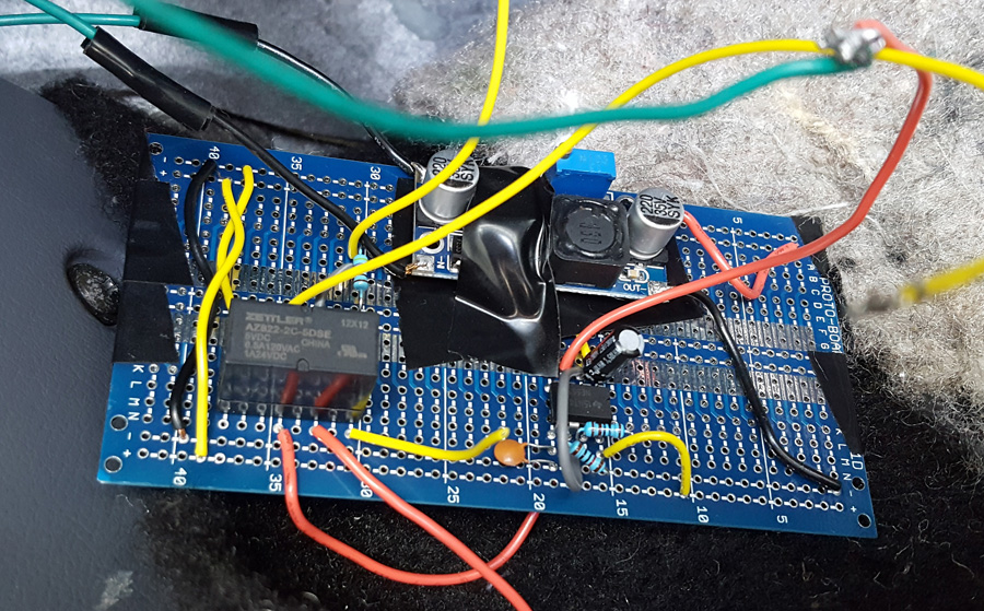
The relay on the left is currently disconnected from everything. On the lower middle is a 555 timer. It outputs at a frequency higher than I would like, but I'm having some issues that I'll explain soon which need to be resolved first I think. The weird PCB just above the 555 timer is a voltage regulator. I'm taking +12V from the car and dropping it down to +5V as measured by a multimeter.
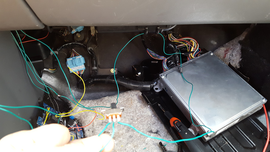
The switch I'm holding, centre goes to ECM, right comes from VSS sensor, and left comes from the 555 timer.
Everything is all torn apart still because I'm having some issues with it, but maybe people who know more about electronics or Insights can weigh in on this issue.
1: I don't know where to find a +5v source, hence the regulator device. If I knew where one was I'd use that instead.
2: When the switch is set to the right, everything works normally, car drives along reading the correct speed. When the switch is set to the left it is SUPPOSED to get a signal from the 555 timer of a square wave and the VSS is cut out of the equation.
Apparently that's not the case.
Observed behaviour when I press the switch to the left is that the car's speedometer still works normally, but auto-stop will never happen. I think the ECM is somehow getting a combined signal at the wrong voltage or something from the VSS and the 555 timer and to play it safe it won't auto stop. I'm absolutely baffled as to how the VSS signal is going through an open switch into the ECM. Does anyone have any ideas what might be going on here?