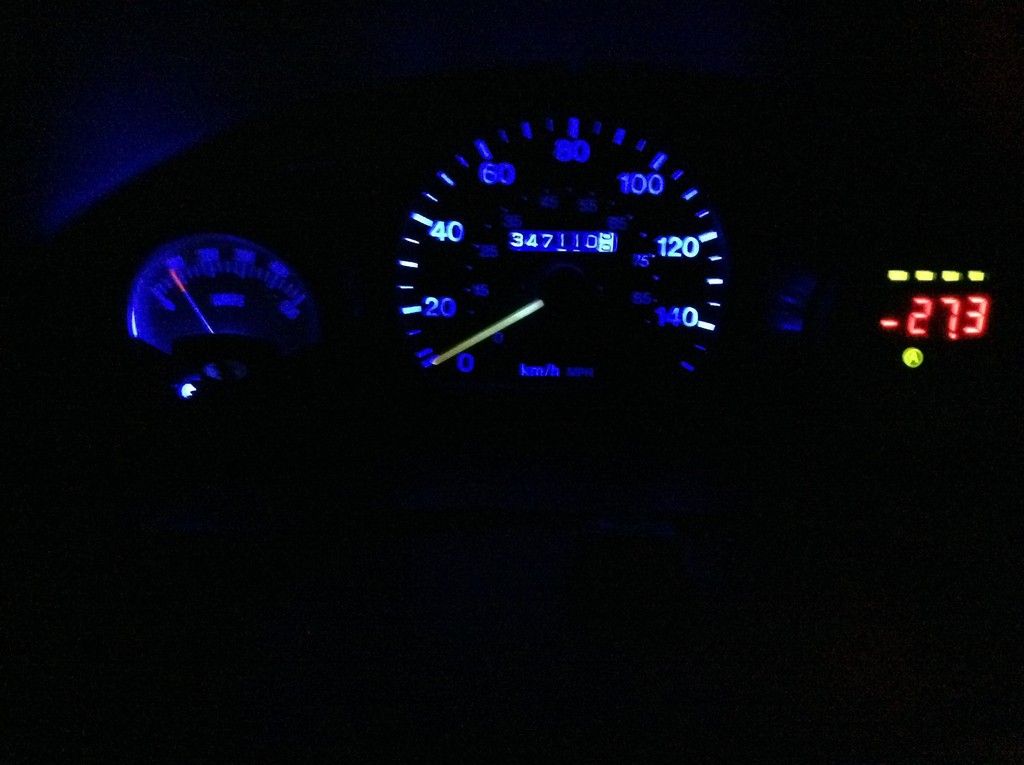
Spent the afternoon wiring in my gauges and their sensors/shunts/scalers.
In order:
1. Battery shunt bus bar to the traction pack negative battery terminal, then out to controller. Sensing wires on either side of shunt to the Link-10 battery monitor.
2. Voltage scaler to + and - traction battery pack terminals, then out to Link-10. (it can't handle over 40 volts without it)
3. Motor shunt bus bar to one motor terminal, the other side of shunt out to the controller. Sensing wires run to the separate ammeter in the instrument cluster.
Preceding this a couple of days ago was re-configuring my + line from the traction pack. It took up the full width of my battery pack as I had the copper bus bars laid out before. I wanted space there to hold the shunt, thus the reconfiguring to make things much more compact. Said line contains the breaker and the contactor before going out to the motor controller.
My current/rough layout:

From left to right (and top to bottom): Battery, Pot-box/breaker/contactor/shunt, controller on heatsink, temporary 12v battery. And yes, what's turning in to a mess of wires.
Motor shunt:

Until I decide on a better way to mount it, anyway.
Checking that everything works:

And a silly little video that shows the motor ammeter in action:
Now I can see exactly what my battery and motor are doing at any given moment.

So if I blow anything up, I'll not have the excuse that I didn't know what was happening under the hood.
