 05-11-2017, 09:24 PM
|
#21 (permalink)
|
|
Aero Deshi
Join Date: Jan 2010
Location: Vero Beach, FL
Posts: 1,065
Thanks: 430
Thanked 669 Times in 358 Posts
|
Hard edges are very tricky because your cap would have to be very well designed to prevent vortex formation. The 12° slope is NOT what you want, it is too steep. Go with 7-
8° and you'll get more storage space, way better lift coefficient (Your truck will fell more planted and stable, and still get 90% of the optimal aerodynamic benefit. Plus it will be way more forgiving of any design errors.
|
|
|

|
 Today Today
|
|
|
|
 Other popular topics in this forum...
|
|
|
|
 05-13-2017, 01:35 PM
|
#22 (permalink)
|
|
Master EcoModder
Join Date: Jan 2008
Location: Sanger,Texas,U.S.A.
Posts: 16,534
Thanks: 24,520
Thanked 7,436 Times in 4,817 Posts
|
campers
Quote:
Originally Posted by freebeard

As much as you can consider the front top and sides to be flat, you can make it out of three triangles (pointing back) and two simple curved conic sections (pointing forward).
Can anyone explain why the NASCAR Camping World Truck Series don't have campers on them?  |
*It's just a rule book thing.They must all meet template limitations mandated by the governing body.
*they'd also be faster and corner better than the NASCAR 'cars',which would too embarrassing.
__________________
Photobucket album: http://s1271.photobucket.com/albums/jj622/aerohead2/
|
|
|

|
 05-13-2017, 01:51 PM
|
#23 (permalink)
|
|
Master EcoModder
Join Date: Jan 2008
Location: Sanger,Texas,U.S.A.
Posts: 16,534
Thanks: 24,520
Thanked 7,436 Times in 4,817 Posts
|
angle 'optimums' are very contextual in nature
Quote:
Originally Posted by Auptimist

I'd be interested to see an A-B-A test of the taller, more gently curved topper that follows that damn template exactly versus the 12° average slope version suggested by that one engineering thesis. I may or may not get around to that. It would be kinda neat if OP and I went with somewhat opposing designs to compare. Definitely slope the rear backwards not forwards though, I agree, and leave an overhang to get that hard edge around the convex section for the fluid tail like aerohead always talks about.
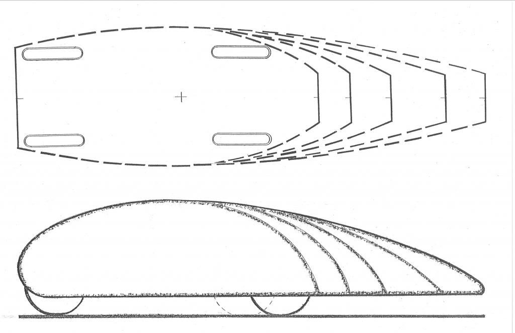
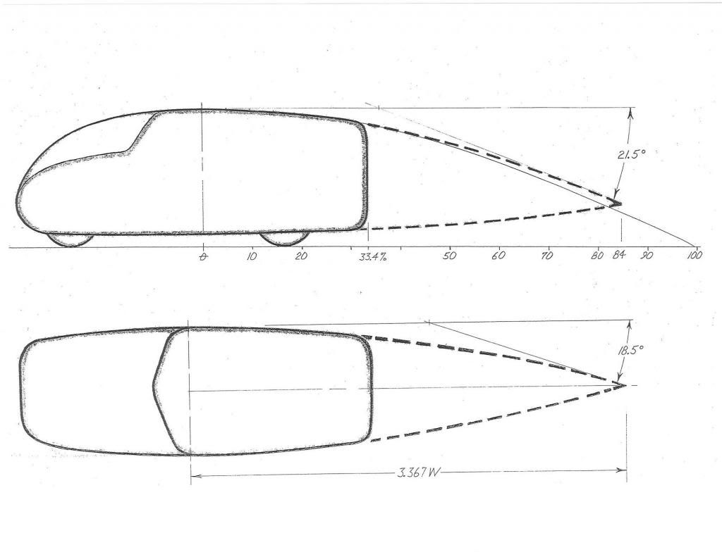
How critical is it to round the joint between the sides and top? It makes sense if the goal is to create an elliptical curve on the backside to induce the "Morelli's Fluid Tail" smoke-ring effect, but it doesn't apply as much if you intend to get the rear edge height close enough to the height of the tailgate. But I also wonder if a hard edge on those "shoulders" to ease construction and purposefully induce flow separation there like the kammbacks' rears (except on top) would be somewhat helpful too. I think it's likely there's a minimum radius for those shoulders below which you're better off with a hard edge. Though as always I'd love for someone to question and point out if/how I'm wrong. Crosswinds may play into it too. (I asked aerohead but he's only on his computer on Saturday mornings haha.)
Attached images are of a quick model from a 3d sketch I made a couple weeks ago in Autodesk Inventor (which for this I prefer over Solidworks). This represents the laziest possible geometry for the aerocap: I lofted the curve of the rear window down a straight 12° slope then trimmed it up. That would require zero heat-forming of the polycarb, just cutting shapes out of a single 4'x8' sheet and solvent/heat welding them together, and bolting them down such that the top section has that longitudinal curve that follows the window curve (which, if I choose to follow it, means I can't have any transverse curvature). Frame discussion in other posts. Sorry for the derail. Again, I'm very curious about your other planned mods!
|
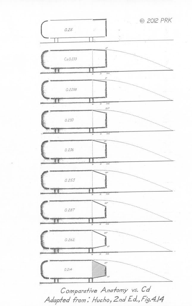
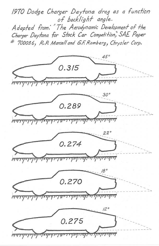
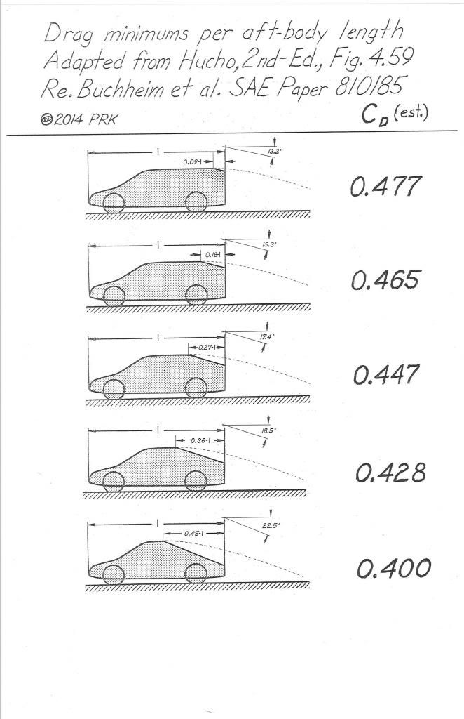
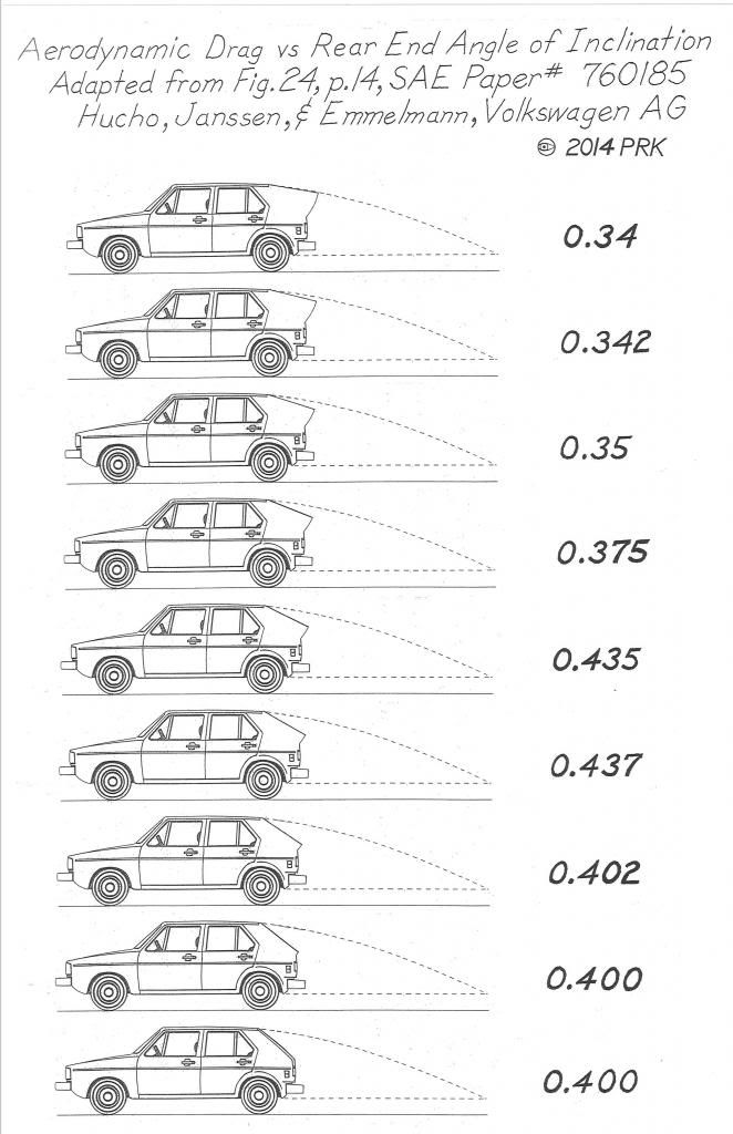
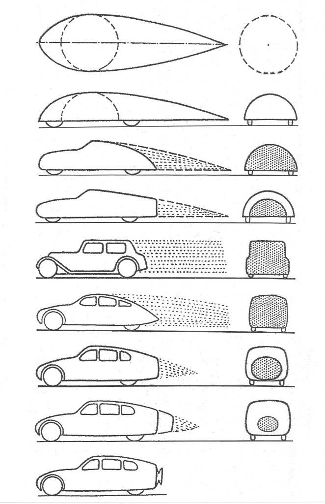
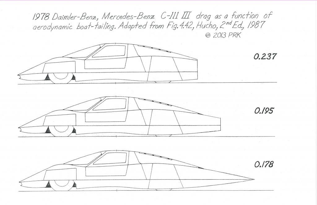
Research has demonstrated that 'optimum' -drag aft-body angles can only be appreciated within the context of a particular vehicle body architecture.
*Type of roof
*Length of roof with respect to overall car length
*Camber
*Tumblehome
*C-pillar design
*Boot,or lack thereof
*etc.
all impact the optimum angle

__________________
Photobucket album: http://s1271.photobucket.com/albums/jj622/aerohead2/
|
|
|

|
|
The Following User Says Thank You to aerohead For This Useful Post:
|
|
 05-13-2017, 03:13 PM
|
#24 (permalink)
|
|
Master EcoModder
Join Date: Aug 2012
Location: northwest of normal
Posts: 29,410
Thanks: 8,365
Thanked 9,124 Times in 7,534 Posts
|
Quote:
|
*It's just a rule book thing.They must all meet template limitations mandated by the governing body.
|
According to the Golden Rule, Camping World makes the rules. They could mandate a slant-chopped canopy with the rear height equal to the those spoiler they use instead.
Quote:
|
*they'd also be faster and corner better than the NASCAR 'cars',which would too embarrassing.
|
That's probably it, can't have that.  |
|
|

|
|
The Following User Says Thank You to freebeard For This Useful Post:
|
|
 05-13-2017, 05:48 PM
|
#25 (permalink)
|
|
EcoModding Lurker
Join Date: Dec 2008
Location: St. Louis
Posts: 45
Thanks: 3
Thanked 3 Times in 2 Posts
|
Thank you for the information! I remember riding in my parent's car in the 1950's (remember vent windows) and sticking my hand outside and trying the exact experiment that you described! What fun that was! My thought about the rear end of a pick-up was based upon my observation of semi-trucks in the rain, e.g., the "burbling effect" of rolling air; hence, trucks have taken to using large bubbles and or "trailer tails" to reduce drag. But your are right: a pickup is not a semi, and the drag issues are different. I will publish a video of my smoke test when done.
|
|
|

|
|
The Following 2 Users Say Thank You to Buddy For This Useful Post:
|
|
 06-04-2017, 01:50 PM
|
#26 (permalink)
|
|
EcoModding Lurker
Join Date: Apr 2017
Location: Nebraska
Posts: 13
Thanks: 1
Thanked 6 Times in 5 Posts
|
Aerohead's comment inspired me to put more thought/effort into my design. Definitely going with rounded corners. I decided I want to run some actual CFD analysis on the Ridgeline but I was unable to find an existing CAD model of the truck, so I started looking for scale models, which are almost as scarce. My plan is to use the 3D scanner at my local maker studio to get an accurate CAD model without having to go through the effort of modeling the truck from scratch. Apparently Matchbox made very limited quantities of it ten years ago and I got lucky to get for $5 the last one in stock outside of eBay it seems. (Plus my inner kid is super excited to have a new toy car!) I'll have to modify the model some, mostly just downizing the wheels and modifying the underbody accordingly. Honda Ridgeline Overland Crew Pickup Truck - Global Diecast Direct
I've yet to decide whether to use Solidworks' or Autodesk's CFD but it will likely be one of those. At first I really wanted to run a optimization program for an aerocap like that 2003 thesis from the Naval Postgraduate School, but... we'll see. |
|
|

|
 06-04-2017, 03:22 PM
|
#27 (permalink)
|
|
Aero Deshi
Join Date: Jan 2010
Location: Vero Beach, FL
Posts: 1,065
Thanks: 430
Thanked 669 Times in 358 Posts
|
Post # 16 is within 5% of optimized for drag, 100% optimized for lift reduction, and it is practical in terms of cargo space and ease of access. Keep in mind that a cap will not take you from 22MPG to 32MPG, more like 24 to 25 MPG tops.
|
|
|

|
 06-04-2017, 05:49 PM
|
#28 (permalink)
|
|
EcoModding Lurker
Join Date: Apr 2017
Location: Nebraska
Posts: 13
Thanks: 1
Thanked 6 Times in 5 Posts
|
Yes, and I'm excited to prove your points with data 
My design priorities:
1. Cd reduction weighed against cost
2. Legality and safety - including visibility
3. Ease of access
4. Aesthetic!
5. Manufacturing difficulty
6. Storage volume when closed up (currently I have a roll-up tonneau and it's been fine - rarely do loads go much higher than the bed walls)
11. Lift
Lift can't get any worse with the addition of a cap than it already is, and it's not a problem as-is 
Another reason I want to run simulations is that the rear bezel of the cab already slopes down, (and is >$100 to replace if I screw it up) and has a really nice slot underneath it where I could tape/compress-into-foam the curved edge of the polycarb up under it (since it's a unibody I don't have to worry much about bed flexure, so it should be able to actually touch there). I want concrete data on how much worse that would be for Cd. I'd hypothesize it would let me get away with the straight profile I posted, since it should create a little vortex right behind the bezel and hopefully attach it right onto the topper, effectively simulating the convex profile. Same for the sides, there's a nice lip that seems pupose-built for this. I could be terribly wrong, but I'll find out before construction. If it works, it would mean my top brake light wouldn't be under tinted polycarb so I don't get pulled over by a bored/curious cop, I might not have to bake the hatch sheet into a compound curve, and I can have a simple triangular frame with attachment points all along. Very hopeful haha
Last edited by Auptimist; 06-04-2017 at 06:40 PM..
|
|
|

|
|