07-05-2009, 03:57 PM
|
#1 (permalink)
|
|
MPGuino Newbie
Join Date: Jun 2009
Location: San Francisco
Posts: 7
Thanks: 0
Thanked 0 Times in 0 Posts
|
 What does an injector signal look like?
I'm connecting MPGuino to a 1990 Toyota 4Runner. My ECM connector pinout is:
E01 No10 STA Vf NSW
E02 No20 IGt E1 n/c
where the pins are described as:
No10: "Injector"
No20: "Injector"
E01: "Engine Ground"
E02: "Engine Ground"
I borrowed an oscilloscope to look at the No10 and E01 signals. The No10 signal was a high pulse (> 12 V), while the E01 signal was a small negative pulse, more like 0.5 V. Both pulse frequencies correspond to changing engine rpm (pressing the gas while sitting in the driveway).
The shorthand directions for finding the Injector signal call for finding the signal which is *not* 12 V, so I connected the E01 signal to the MPGuino, and it doesn't work (no injector pulses are recorded). So the obvious thing to do is try the other pin, but I thought I would check here first, because its a pretty high voltage.
So, in general, what does the MPGuino expect the injector signal to look like? What is the safe input voltage to an input pin on the MPGuino board? The "Injector" signal seems to be a pretty high voltage spike, higher than the ATmega datasheet allows (maybe this what the zener diodes at the input pins are for?).
Given the choice between the two signals in the picture, which one is most likely the correct INJ signal?
Thanks!!
|
|
|

|
 Today Today
|
|
|
|
 Other popular topics in this forum...
|
|
|
|
|
07-06-2009, 03:39 AM
|
#2 (permalink)
|
|
EcoModding Lurker
Join Date: May 2009
Location: Northeast Indiana, USA
Posts: 5
Dora - '98 Ford Explorer XL
Thanks: 0
Thanked 0 Times in 0 Posts
|
You need the Zener diodes in place to drain off extra voltage to the ground line.
As I understand it the Zener acts like an overflow valve, turning those high volt injector pulses into low voltage pulses that the ATMEGA chip can safely handle.
Either [No10: "Injector"] or [No20: "Injector"] is what you want to tap into.
Ideally you want to use the car ground and not the ground on the ATMEGA board.
Here is a simple page I made, mainly as a reference for myself but I was hoping it would help others.
How to build an MPGuino - EcoModder
I created the image on that page because all the other ones I found where kinda confusing. |
|
|
|
|
07-06-2009, 03:55 AM
|
#3 (permalink)
|
|
needs more cowbell
Join Date: Feb 2008
Location: ÿ
Posts: 5,038
Thanks: 158
Thanked 269 Times in 212 Posts
|
mh (nice little rotary btw  ) ,
1. Make sure you measure/tap by the injector for starters, I frequently have problems at the ECU for unknown reasons.
2. Some older cars (and who knows what else) have a positively switched circuit. So that you can locate one (of two) injector leads that will give you an "inverted" gph reading. I added a "inj trig" setting to the setup recently that you can set to 1 to see if that fixes things. If that is what is going on then the first picture looks right.
the atmega has a large resistor in series with the signals and a zener to clamp it at or below 5 volts, it is meant for a 14+ volt injector system. The atmega needs at least 2.5 volts to register an "on" signal, so 0 to 0.5 won't even register.
__________________
WINDMILLS DO NOT WORK THAT WAY!!!
|
|
|
|
|
07-07-2009, 08:06 PM
|
#4 (permalink)
|
|
MPGuino Newbie
Join Date: Jun 2009
Location: San Francisco
Posts: 7
Thanks: 0
Thanked 0 Times in 0 Posts
|
These replies are very helpful, thanks!! That all makes a lot of sense. I will report back after I have a chance to try the No10 signal.
PS - Rotary engines are the engines of the future!
|
|
|
|
|
07-13-2009, 03:43 PM
|
#5 (permalink)
|
|
MPGuino Newbie
Join Date: Jun 2009
Location: San Francisco
Posts: 7
Thanks: 0
Thanked 0 Times in 0 Posts
|
Works great!
Tapped the No10 signal, and the MPGuino is working like a champ. Will post pics and calibration info when complete. Thanks for the advice!
|
|
|
|
|
11-20-2009, 12:31 PM
|
#6 (permalink)
|
|
EcoModding Lurker
Join Date: Nov 2009
Location: UK
Posts: 18
Thanks: 0
Thanked 2 Times in 2 Posts
|
I found this very useful (link below shows injector traces)
Automotive Scope Applications
Last edited by winker; 01-01-2010 at 03:55 PM..
Reason: Seems people did not realise it was a link to injector traces!
|
|
|
|
|
12-27-2009, 11:34 PM
|
#7 (permalink)
|
|
Master EcoModder
Join Date: Jul 2009
Location: New York
Posts: 513
Thanks: 2
Thanked 101 Times in 74 Posts
|
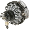
using an injector tester set to pulse 4ms for ever
here is the waveform , but a running system is going to have a much higher voltage spike as the injector coil magnetic field collapses
IF you tamper with the voltage spike you may change the way that injector functions .
which is UNdesireable
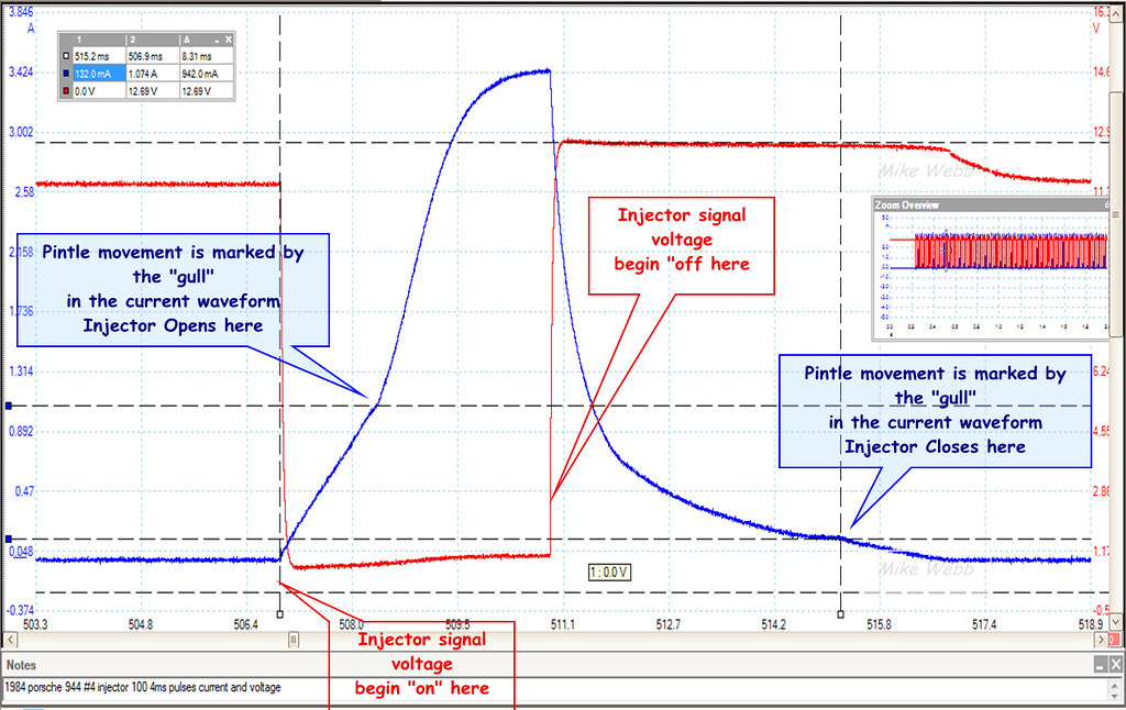
an actual waveform sample from another bank injection system such as a 1990 4runner as in
all injectors operate together at the same time
1994 volvo 850 bank injection
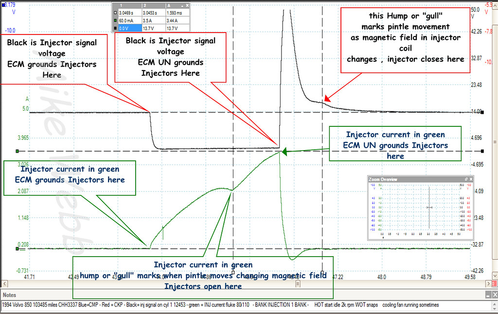
you can clearly see injector pintle movement marking ACTUAL injector closing and opening
Quote:
Originally Posted by mhopeng

I'm connecting MPGuino to a 1990 Toyota 4Runner. My ECM connector pinout is:
E01 No10 STA Vf NSW
E02 No20 IGt E1 n/c
where the pins are described as:
No10: "Injector"
No20: "Injector"
E01: "Engine Ground"
E02: "Engine Ground"
I borrowed an oscilloscope to look at the No10 and E01 signals. The No10 signal was a high pulse (> 12 V), while the E01 signal was a small negative pulse, more like 0.5 V. Both pulse frequencies correspond to changing engine rpm (pressing the gas while sitting in the driveway).
The shorthand directions for finding the Injector signal call for finding the signal which is *not* 12 V, so I connected the E01 signal to the MPGuino, and it doesn't work (no injector pulses are recorded). So the obvious thing to do is try the other pin, but I thought I would check here first, because its a pretty high voltage.
So, in general, what does the MPGuino expect the injector signal to look like? What is the safe input voltage to an input pin on the MPGuino board? The "Injector" signal seems to be a pretty high voltage spike, higher than the ATmega datasheet allows (maybe this what the zener diodes at the input pins are for?).
Given the choice between the two signals in the picture, which one is most likely the correct INJ signal?
Thanks!!
|
Last edited by mwebb; 12-27-2009 at 11:59 PM..
Reason: loaded another image
|
|
|
|
|
12-28-2009, 12:22 AM
|
#8 (permalink)
|
|
needs more cowbell
Join Date: Feb 2008
Location: ÿ
Posts: 5,038
Thanks: 158
Thanked 269 Times in 212 Posts
|
more info here, the pintle can also be observed by minute changes in back voltage.:
In this course we will study and learn about electricity and electronics
Though the cpu power needed to process the waveforms as something other than binary signals is not trivial, and if you were to try it with standard mpguino hardware you would probably not be any more accurate, if even as accurate. The guino is at %50 cpu timing injector pulses in microseconds and displaying the computations.
Mike, can you pick a thread and just link to it from the other one as appropriate? Its a little cross-posty like I should be responding to both threads about the same thing.
__________________
WINDMILLS DO NOT WORK THAT WAY!!!
|
|
|
|
|
12-28-2009, 12:12 PM
|
#9 (permalink)
|
|
Master EcoModder
Join Date: Jul 2009
Location: New York
Posts: 513
Thanks: 2
Thanked 101 Times in 74 Posts
|
i dunno
was i operating outside of protocol ?
two thread s , similar requests , nobody had provided the answer in either one .... so i did .
Quote:
Originally Posted by dcb
more info here, the pintle can also be observed by minute changes in back voltage.:
In this course we will study and learn about electricity and electronics
Though the cpu power needed to process the waveforms as something other than binary signals is not trivial, and if you were to try it with standard mpguino hardware you would probably not be any more accurate, if even as accurate. The guino is at %50 cpu timing injector pulses in microseconds and displaying the computations.
[b]Mike, can you pick a thread and just link to it from the other one as appropriate? Its a little cross-posty like I should be responding to both threads about the same thing. [b/] |
|
|
|
|
|
12-28-2009, 12:54 PM
|
#10 (permalink)
|
|
needs more cowbell
Join Date: Feb 2008
Location: ÿ
Posts: 5,038
Thanks: 158
Thanked 269 Times in 212 Posts
|
no biggie,
the gulls might be discernable with a soundcard interface, but would need to use both channels for the injector, and would not have one left for speed/distance.
__________________
WINDMILLS DO NOT WORK THAT WAY!!!
|
|
|
|
|