Read original here, along with other articles on aerodynamics and testing.
To
test for changes in drag, you will most likely need some sort of throttle position sensor (TPS) display. This helps to ensure that your throttle is open at the same angle during constant-throttle testing or to note the change in throttle angle during constant-speed testing. Heres how I wired a display in my 1991 Toyota pickup.
To Wire or Not to Wire
If you have an OBD2 carmost cars built in or after 1995 or 1996you can read throttle position from a computer (or even an app on your phone) plugged into the OBD port, usually located under the steering column.
 Here's the OBD port on my 2013 Prius.
For those of us with older cars, it isnt as simple. On the truck, Ill have to find the wire that carries the TPS signal to the engine control unit (ECU), tap into it, and send that voltage to a separate display that Ill mount on the dash.
Reading Wiring Diagrams
Before doing anything else, I found and purchased a factory wiring manual for my truck. This one came packaged with a set of factory service manuals, an invaluable resource when you have an older vehicle. Alternatively, you might be able to find a scan or PDF of your cars electrical schematics online, but as always with online resources, be sure you verify the information you find there.

Wiring diagrams usually have multiple sections: drawings of the physical locations of connectors and ground bolts, lists or charts of connectors, and of course the actual wiring diagrams which schematically represent which devices are connected and how. I found the throttle position sensor on the 22RE schematic:
 The TPS is in the center bottom part of the right hand page; the diagram shows three wires that run to the ECU.
If there were multiple engine and transmission options for your car, make sure youre looking at the correct diagram!
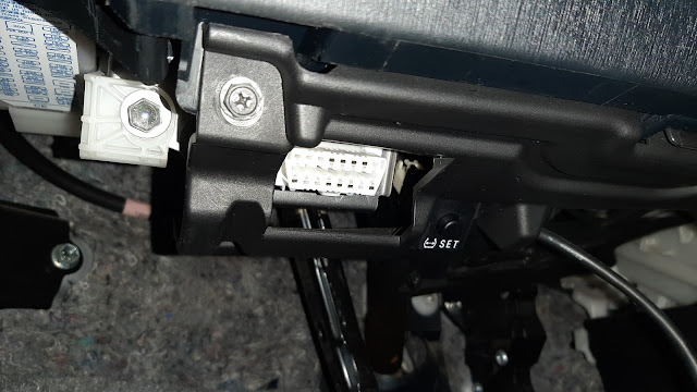
For this truck (and other Toyotas with linear throttle position sensors), its the VTA wire that reports the variable TPS voltage to the ECU, so thats the wire I want to find. The voltage changes linearly with the throttle blade's angle and is sent to the computer; larger throttle opening, higher voltage through that wire. For the 22RE, its marked as yellow, connected to the ECU at pin 11 in the 18-pin connector F. From the location schematic, we can find that the connector is behind the passenger-side kick panel. Here it is:
 Connecting the Display
You have some options as far as tapping into the TPS wire once youve found it. Dont just twist wires together and hope they hold or use wire nut connectors! Wire nuts are fine for home wiring, but cars are a very different environment, and the constant jostling and vibration will work the wire nuts loose and could lead to a short or even a fire.
Do not use them to connect wires in cars.
The easiest way to connect to the TPS wire is by using a wire tap:
 These are available at any hardware store, usually from a variety of manufacturers. If you use them, be sure and get the correct size range for your wiring.
These have a metal blade inside which cuts into the existing wire and a new wire in parallel, connecting the two. I dont like this method as much as soldering, however, which forms a permanent and robust connection between the two wires that is less susceptible to breaking or corroding.
First, Ill strip off about ¼ of insulation; then, Ill split the strands, slip the end of the new wire through, wrap it around, and solder the two together:

And finally, wrap with electrical tape:

Done! Do the same to connect the display to a switched 12V source for power and a constant ground (I used the existing radio wiring, which is inside the dash near where I mounted the display) and you now have a TPS readout:
 ...that just happens to fit perfectly in the unused blank where the AC button would be on higher trims.
I used
these displays and calibrated them using a 9V battery and a multimeter to check for accuracy, adjusting the small potentiometer on the circuit board.
 The potentiometer adjustment is the small screw near the center of the board. Jewelers' screwdrivers can easily adjust screws in these small sizes.
I reconnected the battery and verified that it works:
 I added a factory clock while I was in there.
Its a bit hard to see, but the display reads 2.55V with the throttle pedal partially depressed.
According to what I had read online, TPS voltage on this truck should vary from around 0.5V at idle to 3.8V at WOT. Sure enough, this one displays 0.50V with the throttle pedal released and 3.88V fully depressed. Now, on to aerodynamic testing on the road!


 Today
Today