01-02-2021, 04:47 PM
|
#1 (permalink)
|
|
Banned
Join Date: Nov 2017
Location: Australia
Posts: 2,060
Thanks: 107
Thanked 1,608 Times in 1,137 Posts
|
Interesting paper on historic car aero
|
|
|

|
|
The Following 3 Users Say Thank You to JulianEdgar For This Useful Post:
|
|
 Today Today
|
|
|
|
 Other popular topics in this forum...
|
|
|
|
|
01-04-2021, 12:10 AM
|
#2 (permalink)
|
|
Master EcoModder
Join Date: Aug 2012
Location: northwest of normal
Posts: 29,297
Thanks: 8,334
Thanked 9,092 Times in 7,509 Posts
|
Thanks! The 21s are starting out to be a great decade.  This is unexpected.
Quote:
|
Interestingly, the drag of the [Dymaxion's] nose is almost off-set by a zone of thrust (annulus of negative Cp-X shown in Figure 14 and numerically in the cumulative drag plot in Figure 16) from just behind the nose to the front wheels.
|
My reading of Figure 16 had Cp-X only negative at 15° yaw and only through the front wheelwell area, not forward of it.
They fudged the number to compensate for the blocked off air intake. There's an interesting gotcha in CFD — air inlets and outlets.
edit:
Wait 'til you-know-who gets ahold of this
Quote:
|
Figure 40 (after Hucho[3]) illustrates the two strategies which have been used for aerodynamic shape development. As discussed previously the ‘optimisation’ of a given style has been the traditional approach since the 1960s and has resulted in some substantial reductions in drag. However, and by reference to passenger car drag time-lines such as Figure 36, it can be argued that this technique might now look to be providing diminishing returns and that a return to the radical approach of the 1930s may be required for worthwhile gains to be achieved. In this alternative process the starting points are scientifically created low-drag aerodynamic forms which are then developed into new generations of passenger vehicles.... So if starting from streamlined forms is to become a strategy once again then the role of the designer to aid the aerodynamicist is crucial.
|
We'd be hearing about 'Paris dress-makers' again.
__________________
.
.Without freedom of speech we wouldn't know who all the idiots are. -- anonymous poster
___________________
.
.Impossible is just something we haven't done yet. -- Langley Outdoors Academy
Last edited by freebeard; 01-04-2021 at 12:21 AM..
|
|
|
|
|
The Following 2 Users Say Thank You to freebeard For This Useful Post:
|
|
|
01-04-2021, 01:13 AM
|
#3 (permalink)
|
|
Banned
Join Date: Nov 2017
Location: Australia
Posts: 2,060
Thanks: 107
Thanked 1,608 Times in 1,137 Posts
|
Quote:
Originally Posted by freebeard

We'd be hearing about 'Paris dress-makers' again.
|
Probably. But I bet he won't mention this:
At 15° yaw, the aerodynamic characteristics are less than ideal with a high front lift and a yawing moment which is 32% higher than would be considered acceptable for a European passenger car of today. |
|
|
|
|
The Following 2 Users Say Thank You to JulianEdgar For This Useful Post:
|
|
|
01-04-2021, 02:29 AM
|
#4 (permalink)
|
|
Master EcoModder
Join Date: Aug 2012
Location: northwest of normal
Posts: 29,297
Thanks: 8,334
Thanked 9,092 Times in 7,509 Posts
|
That's a knock on the Dymaxion. Bucky claimed the cross-wind twitchyness could be driven out if the driver/pilot (it was an omnidirectional transport, he considered it ground taxiing) was properly trained. IIRC the yaw was into the wind, not downwind.
Myself, I'd go to a triangular hull like the ME-262 or Evation ALICE.
__________________
.
.Without freedom of speech we wouldn't know who all the idiots are. -- anonymous poster
___________________
.
.Impossible is just something we haven't done yet. -- Langley Outdoors Academy
|
|
|
|
|
01-04-2021, 02:43 AM
|
#5 (permalink)
|
|
Banned
Join Date: Nov 2017
Location: Australia
Posts: 2,060
Thanks: 107
Thanked 1,608 Times in 1,137 Posts
|
Quote:
Originally Posted by freebeard
That's a knock on the Dymaxion. Bucky claimed the cross-wind twitchyness could be driven out if the driver/pilot (it was an omnidirectional transport, he considered it ground taxiing) was properly trained. IIRC the yaw was into the wind, not downwind.
Myself, I'd go to a triangular hull like the ME-262 or Evation ALICE.
|
yes, I'd be pretty confident that any shape like the Dymaxion or The Template would have pretty bad lift / yaw stability characteristics. |
|
|
|
|
01-04-2021, 04:03 AM
|
#6 (permalink)
|
|
Master EcoModder
Join Date: Aug 2012
Location: northwest of normal
Posts: 29,297
Thanks: 8,334
Thanked 9,092 Times in 7,509 Posts
|
But they could fly better than a Pinto.
I've been reading more, the Conclusion quotes six design patterns from Lay in the 1930s.
Quote:
Suggestions Offered to Car Builders
1. Remove all barnacles or wind-claws from the car. If they cannot be removed, build the body out to enclose them.
2. Replace all sharp edges and radii and corners with round edges and corners of generous radii.
3. Build the front of the vehicle to bore a hole through the air with the least possible disturbance of the surrounding air.
4. Build the rear of the body to lay the air back in place without eddies or turbulence.
5. The shape for the ideal streamline form naturally provides space for the housing of the engine at the rear.
6. The public is becoming streamline conscious and will welcome these changes at a more rapid rate than ever before.
|
I'm trying to figure out the significance of Figures 14 and 15. I can see separating out the X and Z vectors, but the blue bottom in 15. is that a ground interaction?
__________________
.
.Without freedom of speech we wouldn't know who all the idiots are. -- anonymous poster
___________________
.
.Impossible is just something we haven't done yet. -- Langley Outdoors Academy
Last edited by freebeard; 01-04-2021 at 04:22 AM..
|
|
|
|
|
01-04-2021, 04:15 AM
|
#7 (permalink)
|
|
Banned
Join Date: Nov 2017
Location: Australia
Posts: 2,060
Thanks: 107
Thanked 1,608 Times in 1,137 Posts
|
Quote:
Originally Posted by freebeard
But they could fly better than a Pinto.
I've been reading more, the Conclusion quotes six design patterns from Lay in the 1930s.
I'm trying to figure out the significance of Figures 14 and 15. I can see separating out the X and Z vectors, but the blue bottom in 15. is that a ground interaction? |
I can't help - I only skimmed it. Might come back to it later in the week - hopefully someone else can help. |
|
|
|
|
The Following User Says Thank You to JulianEdgar For This Useful Post:
|
|
|
01-04-2021, 04:29 AM
|
#8 (permalink)
|
|
Master EcoModder
Join Date: Aug 2012
Location: northwest of normal
Posts: 29,297
Thanks: 8,334
Thanked 9,092 Times in 7,509 Posts
|
No worries.
I'm off down another rabbit hole. I used the term 'design pattern' and landed on applied.math.utsa.edu: SOME NOTES ON CHRISTOPHER ALEXANDER and the book The Nature of Order. Maybe I can find an audio book, my eyes aren't that great lately.
__________________
.
.Without freedom of speech we wouldn't know who all the idiots are. -- anonymous poster
___________________
.
.Impossible is just something we haven't done yet. -- Langley Outdoors Academy
|
|
|
|
|
01-04-2021, 10:19 AM
|
#9 (permalink)
|
|
Moderator
Join Date: Feb 2012
Location: Urbana, IL
Posts: 1,939
Thanks: 199
Thanked 1,807 Times in 943 Posts
|
Quote:
Originally Posted by freebeard
My reading of Figure 16 had Cp-X only negative at 15° yaw and only through the front wheelwell area, not forward of it.
|
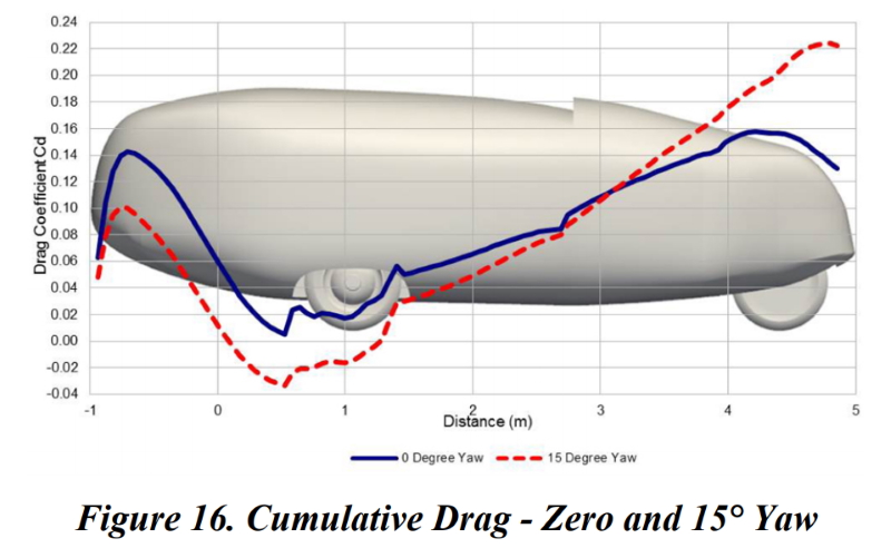
The key here is the slope of the line, which tells you how drag varies (and how much) with length. From the rounded corners back, at both 0 and 15 degrees, the negative slope shows that the x-component of pressure is negative (i.e. it's producing thrust). You can see this in Fig. 14, where the large green area on the body in front of the wheels shows a negative (i.e. forward-directed) x-component of pressure.
Quote:
Originally Posted by freebeard
I'm trying to figure out the significance of Figures 14 and 15. I can see separating out the X and Z vectors, but the blue bottom in 15. is that a ground interaction?
|
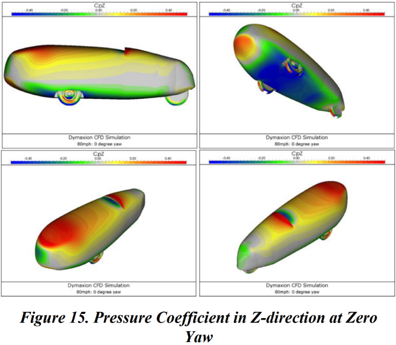
Perhaps, but this figure doesn't actually tell us that. It shows that there is a negative z-component of pressure over much of the underside, but it doesn't say why (and I don't believe the authors say either).
|
|
|
|
|
The Following 2 Users Say Thank You to Vman455 For This Useful Post:
|
|
|
01-04-2021, 12:37 PM
|
#10 (permalink)
|
|
Master EcoModder
Join Date: Aug 2012
Location: northwest of normal
Posts: 29,297
Thanks: 8,334
Thanked 9,092 Times in 7,509 Posts
|
Quote:
|
The key here is the slope of the line, which tells you how drag varies...
|
Thanks, I was oblivious to the slope.
__________________
.
.Without freedom of speech we wouldn't know who all the idiots are. -- anonymous poster
___________________
.
.Impossible is just something we haven't done yet. -- Langley Outdoors Academy
|
|
|
|
|