 09-17-2017, 04:18 AM
|
#11 (permalink)
|
|
Master EcoModder
Join Date: Sep 2009
Location: Ireland
Posts: 734
Thanks: 26
Thanked 304 Times in 171 Posts
|
I know this is probably a super long shot but does anyone have any information on the temperature sensors used in the large rear tesla drive unit? I have measured room temperature resistance and observed the resistance drops with increasing temperature but that's it. My plan is to start running coolant through the motor / inverter and plot a few points of resistance versus temperature. Any help much appreciated 
__________________
Now, Cole, when you shift the gear and that little needle on the ammeter goes into the red and reads 2000 Amps, that's bad.
www.evbmw.com
|
|
|

|
 Today Today
|
|
|
|
 Other popular topics in this forum...
|
|
|
|
|
09-17-2017, 08:16 AM
|
#12 (permalink)
|
|
Master EcoModder
Join Date: Sep 2009
Location: Ireland
Posts: 734
Thanks: 26
Thanked 304 Times in 171 Posts
|
__________________
Now, Cole, when you shift the gear and that little needle on the ammeter goes into the red and reads 2000 Amps, that's bad.
www.evbmw.com
|
|
|
|
|
09-17-2017, 11:36 AM
|
#13 (permalink)
|
|
Master EcoModder
Join Date: Sep 2010
Location: Saskatoon, canada
Posts: 1,488
Thanks: 749
Thanked 565 Times in 447 Posts
|
Quote:
Originally Posted by jackbauer

I know this is probably a super long shot but does anyone have any information on the temperature sensors used in the large rear tesla drive unit? I have measured room temperature resistance and observed the resistance drops with increasing temperature but that's it. My plan is to start running coolant through the motor / inverter and plot a few points of resistance versus temperature. Any help much appreciated |
Sorry - no direct knowledge here!
Much of industry just uses 100 ohm platinum RTDs. Based on the required temperatures (-40C -> 110C or so) it is the easiest. Do you have 2-wires or 3?
The other common sensor based on the temperature range is J type thermocouples. Those are different - they generate a small voltage difference from dissimilar metals welded together. You almost need to bring the signal into an op-amp to measure it.
__________________
In THEORY there is no difference between Theory and Practice
In PRACTICE there IS!
|
|
|
|
|
09-17-2017, 01:01 PM
|
#14 (permalink)
|
|
Master EcoModder
Join Date: Aug 2012
Location: northwest of normal
Posts: 27,702
Thanks: 7,777
Thanked 8,586 Times in 7,070 Posts
|
Quote:
|
Thanks for the support guys.
|
Well, thank you for supporting Ecomodder. That you would post here is a good testimonial.
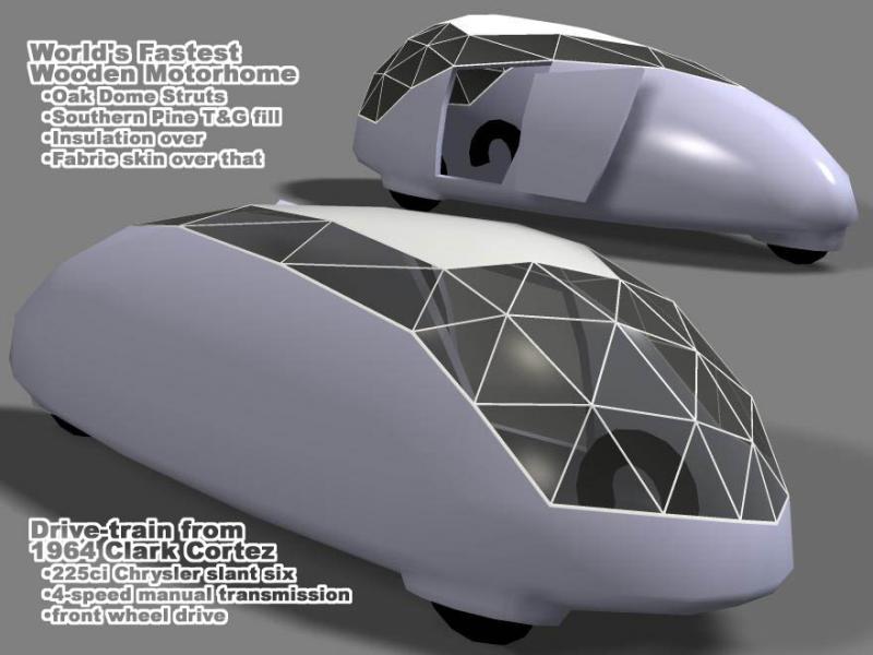
I will watch the back-and-forth between you and thingstodo with interest. The Tesla drivetrain replaces the Chrysler slant-6 in my motorhome design.
|
|
|
|
|
09-18-2017, 10:57 AM
|
#15 (permalink)
|
|
Master EcoModder
Join Date: Sep 2009
Location: Ireland
Posts: 734
Thanks: 26
Thanked 304 Times in 171 Posts
|
Started getting to grips with the front drive unit board today for a few hours. Current sensors are plain vanilla analog and output +/- 2mV/Amp and sit on 2.5v at zero current. Was a tour de force to get the pcb off. Had to use the hot air station to melt the solder on the current sensors. Anyway , got it without damaging the sensors and started getting the pcb outline and locations in progress.
I'm getting together quite a collection of "scrap" Tesla logic boards
__________________
Now, Cole, when you shift the gear and that little needle on the ammeter goes into the red and reads 2000 Amps, that's bad.
www.evbmw.com
|
|
|
|
|
09-22-2017, 01:59 PM
|
#16 (permalink)
|
|
Master EcoModder
Join Date: Sep 2009
Location: Ireland
Posts: 734
Thanks: 26
Thanked 304 Times in 171 Posts
|
On the subject of small motors , I got the pcb footprint sorted today. I've uploaded a dxf over on github for anyone interested. Schematic in progress.
__________________
Now, Cole, when you shift the gear and that little needle on the ammeter goes into the red and reads 2000 Amps, that's bad.
www.evbmw.com
|
|
|
|
|
The Following User Says Thank You to jackbauer For This Useful Post:
|
|
|
09-23-2017, 06:32 AM
|
#17 (permalink)
|
|
Master EcoModder
Join Date: Sep 2009
Location: Ireland
Posts: 734
Thanks: 26
Thanked 304 Times in 171 Posts
|
So working on the front drive unit logic board. Right now , I have most of the functions of the 24 way interface connector from the logic to the driver board worked out but there are a few I'm not sure about. Have a look at the attached pinout and tell me what I'm missing
__________________
Now, Cole, when you shift the gear and that little needle on the ammeter goes into the red and reads 2000 Amps, that's bad.
www.evbmw.com
|
|
|
|
|
The Following User Says Thank You to jackbauer For This Useful Post:
|
|
|
09-23-2017, 12:29 PM
|
#18 (permalink)
|
|
Master EcoModder
Join Date: Sep 2009
Location: Ireland
Posts: 734
Thanks: 26
Thanked 304 Times in 171 Posts
|
Very tight on board space with this one
__________________
Now, Cole, when you shift the gear and that little needle on the ammeter goes into the red and reads 2000 Amps, that's bad.
www.evbmw.com
|
|
|
|
|
The Following User Says Thank You to jackbauer For This Useful Post:
|
|
|
09-25-2017, 11:30 AM
|
#19 (permalink)
|
|
Master EcoModder
Join Date: Sep 2009
Location: Ireland
Posts: 734
Thanks: 26
Thanked 304 Times in 171 Posts
|
So I completed the layout of the small front motor logic board today. Going to wait a week or so before ordering boards as it's not a question of if I have made mistakes just how many. Not sure if the logic boards are the same in the small front and rear motors as yet.
Schematics and some support files are up on the github. I won't release the pcb files until I at least make sure I'm not shorting out the 12v supply
__________________
Now, Cole, when you shift the gear and that little needle on the ammeter goes into the red and reads 2000 Amps, that's bad.
www.evbmw.com
|
|
|
|
|
The Following User Says Thank You to jackbauer For This Useful Post:
|
|
|
09-30-2017, 11:39 AM
|
#20 (permalink)
|
|
Master EcoModder
Join Date: Sep 2009
Location: Ireland
Posts: 734
Thanks: 26
Thanked 304 Times in 171 Posts
|
Had some fun figuring out the large drive unit temperature sensors today
__________________
Now, Cole, when you shift the gear and that little needle on the ammeter goes into the red and reads 2000 Amps, that's bad.
www.evbmw.com
|
|
|
|
|
The Following User Says Thank You to jackbauer For This Useful Post:
|
|
|


