One of the control boards has been tested. My friend is mailing it to me this weekend. I'll need to add a zener diode, since I forgot to mail enough of those to him. But, most everything is working as it should. I say MOST everything because the throttle wasn't varying the PWM signal from 0 to 100%. I couldn't really test the code completely before mailing him the chip, so that should be pretty easy to fix. Here's his report:
-The idle LED blinks
-The contactor FET Q1 turns on/off at the same idle Led blink rate
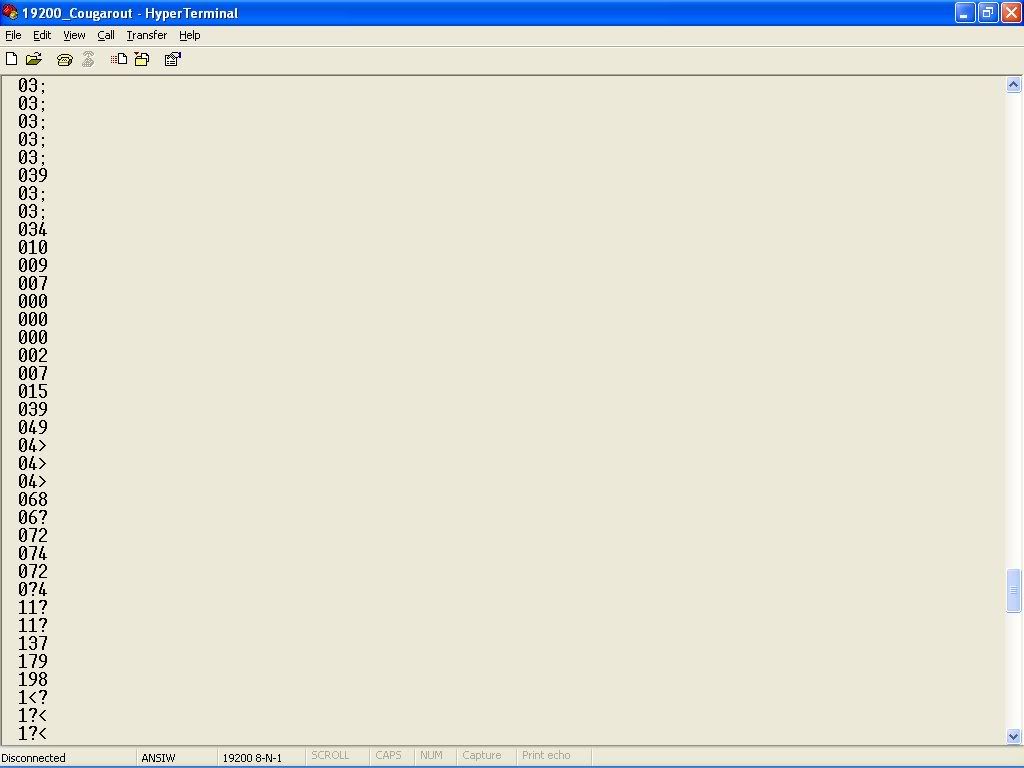
-The RS232 message comes across. 3 characters reflecting motor current. I change a variable voltage source fed into J3-pin2 and watch the message change as I adjusted.
- FET driver output matches PWM from micro @15.66Khz. I still have the same problem with the limited range of throttle pot. The Pot is 5K, R8 is 2K and R10 is 4.7K. These form the voltage divider seen by the micro. I measured the voltage range at R10 at 2.02V to 3.48V when adjusting the pot to either extreme.
I have plenty of scope snapshots and info that I’ll put in a report to go along with it. I finished updating schematic and Gerbers to reflect hole size changes and the swapped comparator input. R16 changes from 1K to 3K.
Here's a screen shot of the current. I sent it as hex since it's so much faster doing % and / with powers of 2. ya!