 06-11-2009, 11:41 AM
|
#1671 (permalink)
|
|
Master EcoModder
Join Date: Jun 2008
Location: London, Ontario
Posts: 1,096
Thanks: 0
Thanked 17 Times in 14 Posts
|
charlie, i would suggest doing an update before doing any work and before committing. Updating all day long is not a problem and can't goof anything up (unless you have a hard time merging).
ps - i hate svn. I have been using it for two years with no instruction and i'm just getting the hang of it (about 20% of its features).
|
|
|

|
 Today Today
|
|
|
|
 Other popular topics in this forum...
|
|
|
|
|
06-11-2009, 02:50 PM
|
#1672 (permalink)
|
|
PaulH
Join Date: Feb 2008
Location: Maricopa, AZ (sort of. Actually outside of town)
Posts: 3,832
Thanks: 1,362
Thanked 1,202 Times in 765 Posts
|
One of the control boards has been tested. My friend is mailing it to me this weekend. I'll need to add a zener diode, since I forgot to mail enough of those to him. But, most everything is working as it should. I say MOST everything because the throttle wasn't varying the PWM signal from 0 to 100%. I couldn't really test the code completely before mailing him the chip, so that should be pretty easy to fix. Here's his report:
-The idle LED blinks
-The contactor FET Q1 turns on/off at the same idle Led blink rate
-The RS232 message comes across. 3 characters reflecting motor current. I change a variable voltage source fed into J3-pin2 and watch the message change as I adjusted.
- FET driver output matches PWM from micro @15.66Khz. I still have the same problem with the limited range of throttle pot. The Pot is 5K, R8 is 2K and R10 is 4.7K. These form the voltage divider seen by the micro. I measured the voltage range at R10 at 2.02V to 3.48V when adjusting the pot to either extreme.
I have plenty of scope snapshots and info that I’ll put in a report to go along with it. I finished updating schematic and Gerbers to reflect hole size changes and the swapped comparator input. R16 changes from 1K to 3K.
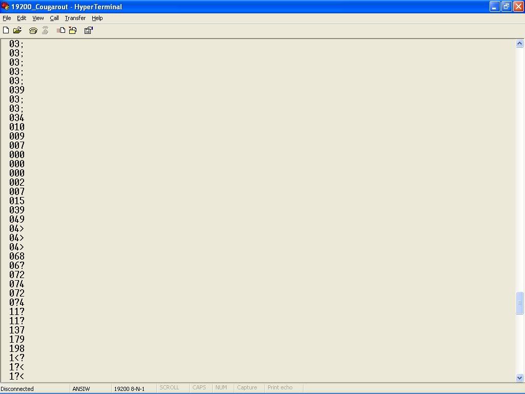
Here's a screen shot of the current. I sent it as hex since it's so much faster doing % and / with powers of 2. ya!
 |
|
|
|
|
06-11-2009, 05:58 PM
|
#1673 (permalink)
|
|
EcoModding Lurker
Join Date: Jun 2009
Location: Isle of Man
Posts: 8
Thanks: 0
Thanked 1 Time in 1 Post
|
Hello all. Fantastic job so far. Just a quick pointer, the capacitor C10 on controller board rev.2B is wrong polarity. Should be neg to U4 pin 6.
Also, what's the purpose of U9 (opto)? - +12VB and +5V are not isolated anyway via U1
I really don't want to come across as picky, I'm just saying.
Anyway, great work, keep it up.
Rob
|
|
|
|
|
06-11-2009, 06:18 PM
|
#1674 (permalink)
|
|
PaulH
Join Date: Feb 2008
Location: Maricopa, AZ (sort of. Actually outside of town)
Posts: 3,832
Thanks: 1,362
Thanked 1,202 Times in 765 Posts
|
EDIT: Hey, the awesome engineer has been checking the thread, and has responded! Just for future reference, I'm pretty much actually a moron that doesn't really what I'm talking about. hehe.
The .1uf caps around the HIN202 are all ceramics and therefore nonpolarized. This was the default shape Protel had for nonpolarized (note no + sign) and I wasn't concerned about the curved side of symbol. Personally, I like both sides of the shape straight for nonpolarized.
Optoisolator U9 is necessary. +12VB is on the "dirty" side of common mode filter L1 and I need to keep it isolated. Both the +12VB and +5V also reference difference grounds, also separated by the common mode filter, but the +12VB ground is also a diode drop lower thanks to D1. A 20 cent opto handles the level shifting and isolation. We'd require an NPN transistor anyway to turn the FET on.
Ya! hehe. I got good peeps!
Last edited by MPaulHolmes; 06-11-2009 at 09:57 PM..
|
|
|
|
|
06-12-2009, 01:32 AM
|
#1675 (permalink)
|
|
EcoModding Lurker
Join Date: Jun 2009
Location: Seattle, Wa
Posts: 71
Thanks: 7
Thanked 31 Times in 26 Posts
|
Howdy Paul and all of Yall!!!
WOW
.  I must say this is the LONGEST thread on any board I have ever read from start to finish and also the most informative and entertaining.
I have not started my own EV project yet because I still had some parts to find and build and up until I found this thread I had not decided on a controller. I have signed up to be part of the buy in bulk group purchase of parts and am looking forward to making my very first wheel go round. ;-)
I have a question for you guys concerning the abilities of the controller. My project is going to be a long one and also a ground up build. I am not looking to convert to but rather build from scratch an electric car that I have had in mind for a few years.
The controller I would like to build for this car will not only make her go but also control shift points for an automatic transmission I am building now. Anyway I am wondering if the ATmega8 or the others in its line have the ability to control some variable ratio valves the transmission will use to effect the shift points.
Also I would like to be able to remove the controller from a dock for security. So is it possible to connect the controller part to the actual drive side of this setup through something like a CAT5 cable?
Thank You Paul for undertaking this daunting task and thank you all for helping him make it happen. I wish I had found this thread when it started.
Cyrus  |
|
|
|
|
06-12-2009, 02:12 AM
|
#1676 (permalink)
|
|
PaulH
Join Date: Feb 2008
Location: Maricopa, AZ (sort of. Actually outside of town)
Posts: 3,832
Thanks: 1,362
Thanked 1,202 Times in 765 Posts
|
Hey Cyruscosmo! Do you mean having the logic of an automatic transmission? What signal would need to be sent from the controller to cause a shift? I would guess that RPM would be the deciding factor for shifting. I don't think it would be that hard to get an RPM sensor on the motor, and to make the controller become aware of the RPM. Then it could send signals out whenever the RPM reached a certain point, which could cause the shift. It sounds relatively straightforward. The nice thing about programming is that you can do pretty much whatever you want! It is only 16 MHz, but I was thinking of changing it to an ATMega168, which can be 20 MHz (wow, what is this, 1990?).
I'm guessing that a CAT5 cable would have too high an impedance. You need pretty big copper ribbon wire with lots of surface area to connect the ground of the mosfet driver (which is on the control board in this version) to the ground of the power section. I'm sure the control board can be made plug and play. Nothing is in stone!
|
|
|
|
|
06-12-2009, 03:14 AM
|
#1677 (permalink)
|
|
PaulH
Join Date: Feb 2008
Location: Maricopa, AZ (sort of. Actually outside of town)
Posts: 3,832
Thanks: 1,362
Thanked 1,202 Times in 765 Posts
|
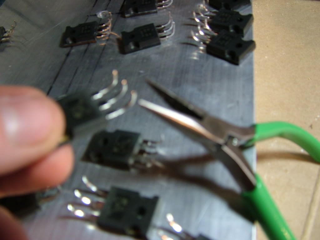
OK all, I have a little question. The diodes will be surface mounted at this point. I need a good way to bend the legs to give them a little flex to handle the tiny expansion from heating. They will be clamped to the back of a heat spreader with about 15 pounds of force, so maybe the diodes will have a hair of ability to move if the legs get longer by like a micron or something from the heating? I've been bending them as follows:
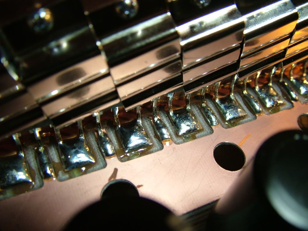
Here's what it looks like with the diodes soldered:
Ian of Zero Emissions Vehicles Australia does his like this:

That's a problem for me, since my middle bus bar is wider than his and the legs would bump into the bus bar. Oh the humanity. I could shave back the bus bar a bit I guess. What do you guys think? |
|
|
|
|
06-12-2009, 05:05 AM
|
#1678 (permalink)
|
|
EcoModding Lurker
Join Date: May 2009
Location: Bucharest,RO and Copenhagen,DK
Posts: 42
Thanks: 0
Thanked 1 Time in 1 Post
|
You can use the bend Ian was using but start towards exterior. On the other hand I have asked a couple of friends and they agreed that it should not make a difference: if there was some recomandation for this it should be in the manufacturer datasheet.
Last edited by charlie_fd; 06-12-2009 at 05:21 AM..
|
|
|
|
|
06-12-2009, 07:51 AM
|
#1679 (permalink)
|
|
EcoModding Apprentice
Join Date: May 2009
Location: Australia
Posts: 109
Thanks: 0
Thanked 2 Times in 2 Posts
|
For what it is worth I agree with Charlie, I have seen an awful lot of electronics over the years and can't remember anyone going to the effort of bending legs.
The devices are designed to be through hole mounted after all. I think vibration would be a bigger worry than expansion. It is probably not to hard to work out how far copper will expand with a temperature change, I am guessing it is a known factor. If it turns out to be 5 microns I can't see it being an issue.
|
|
|
|
|
06-12-2009, 09:01 AM
|
#1680 (permalink)
|
|
EcoModding Apprentice
Join Date: May 2009
Location: Orrville, Ohio
Posts: 108
Thanks: 9
Thanked 2 Times in 2 Posts
|
The game is very much afoot Mr Holmes. Am getting an education in electronics. Keep up the good work. Take care,Watt 
|
|
|
|
|


