Yes, thank you! I screwed up the schematic.

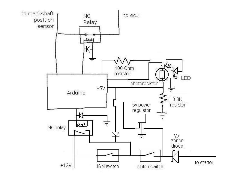
I knew what I wanted to do but omitted a pretty vital wire haha. Basically, I'm sending a 5V signal to the clutch switch to watch to see if its pressed. The zener would block this signal voltage from going to the starter and having it eat up power. However, it would allow the 12V to pass by when the starter needed to be used. The 5V regulator simply protects the input on the arduino from 12V power when the starter is going to be used.
Here is an updated schematic to show what I intended.

However, last night I grabbed an extra starter I had on hand (yeah, I got a lot of spare parts

). I powered up the starter solenoid and while I didn't measure the power requirements, I can tell its drawing a good deal of power. It is quite the violent slam and its not exactly moving a tiny bit of weight. I'm guessing I'll need at least something capable of handling a 5-10A spike load to be safe. Here is a pic of the setup. I think I'm going to need something much beefier than a few 5W zener diodes unless they can handle a quick spike? Unfortunately, I have no way of measuring the amp spike.
