Go Back   EcoModder Forum > EcoModding > EcoModding Central
Register Now
 Register Now
 

Reply  Post New Thread
 
Submit Tools LinkBack Thread Tools
Old 03-16-2011, 08:27 AM   #21 (permalink)
Wiki Writer
 
Join Date: Jul 2010
Location: Melbourne, Australia
Posts: 236

bugler - '91 Mazda 626
90 day: 35.89 mpg (US)
Thanks: 15
Thanked 25 Times in 22 Posts
daox, sounds like a good project,
since you asked for electronic info i thought i might chime in.
From your schematic i am not exactly sure what your planing to do with the 5v power regulator and zener diode, sort of seems like your trying to power the starter with the 5v power regulator. Might be good to explain this a bit maybe i can offer a better solution which doesn't require the zener

anyway you would be correct in assuming the zeners wont current share exactly however they will current share a bit. It completely depends on the tolerance of the current / voltage relationship. zeners are not perfect so if you have a 6v zener it will actually start conducting very small currents down at say 5.5v and slowly increase current and say if you were putting through 10 amps through the zener it might drop maybe 6.5v instead of exactly 6. So in general terms if you parallel them if one zener takes more current its voltage will go up and in turn the other zener will be able to take more current due to the higher voltage. Sorry for the confusing explanation that is just how i think about components when evaluating current sharing.

Anyway all zeners wont have the exact same voltage / current curve so each of the voltages for a given current will be slightly different so the current will not share perfectly but it will not all be forced into one zener.

So if you didn't understand any of that, try it out just allow some extra head room in the power estimates because they wont share perfectly

  Reply With Quote
The Following User Says Thank You to saand For This Useful Post:
Daox (03-16-2011)
Alt Today
Popular topics

Other popular topics in this forum...

   
Old 03-16-2011, 10:28 AM   #22 (permalink)
Administrator
 
Daox's Avatar
 
Join Date: Dec 2007
Location: Germantown, WI
Posts: 11,203

CM400E - '81 Honda CM400E
90 day: 51.49 mpg (US)

Daox's Grey Prius - '04 Toyota Prius
Team Toyota
90 day: 49.53 mpg (US)

Daox's Insight - '00 Honda Insight
90 day: 64.33 mpg (US)

Swarthy - '14 Mitsubishi Mirage DE
Mitsubishi
90 day: 56.69 mpg (US)

Daox's Volt - '13 Chevrolet Volt
Thanks: 2,501
Thanked 2,586 Times in 1,554 Posts
Yes, thank you! I screwed up the schematic. I knew what I wanted to do but omitted a pretty vital wire haha. Basically, I'm sending a 5V signal to the clutch switch to watch to see if its pressed. The zener would block this signal voltage from going to the starter and having it eat up power. However, it would allow the 12V to pass by when the starter needed to be used. The 5V regulator simply protects the input on the arduino from 12V power when the starter is going to be used.

Here is an updated schematic to show what I intended.


However, last night I grabbed an extra starter I had on hand (yeah, I got a lot of spare parts ). I powered up the starter solenoid and while I didn't measure the power requirements, I can tell its drawing a good deal of power. It is quite the violent slam and its not exactly moving a tiny bit of weight. I'm guessing I'll need at least something capable of handling a 5-10A spike load to be safe. Here is a pic of the setup. I think I'm going to need something much beefier than a few 5W zener diodes unless they can handle a quick spike? Unfortunately, I have no way of measuring the amp spike.

__________________
Current project: A better alternator delete
  Reply With Quote
Old 03-16-2011, 09:01 PM   #23 (permalink)
EcoModding Apprentice
 
piers.singer's Avatar
 
Join Date: Feb 2010
Location: Sussex/Kent, UK
Posts: 108
Thanks: 4
Thanked 23 Times in 12 Posts
This is an excellent project, Daox, very interesting.
__________________
Spoken like a champion. Oh no, disaster!
  Reply With Quote
Old 03-17-2011, 10:15 AM   #24 (permalink)
Administrator
 
Daox's Avatar
 
Join Date: Dec 2007
Location: Germantown, WI
Posts: 11,203

CM400E - '81 Honda CM400E
90 day: 51.49 mpg (US)

Daox's Grey Prius - '04 Toyota Prius
Team Toyota
90 day: 49.53 mpg (US)

Daox's Insight - '00 Honda Insight
90 day: 64.33 mpg (US)

Swarthy - '14 Mitsubishi Mirage DE
Mitsubishi
90 day: 56.69 mpg (US)

Daox's Volt - '13 Chevrolet Volt
Thanks: 2,501
Thanked 2,586 Times in 1,554 Posts
Thanks piers.singer. I hope it works good.

Anyway, I think I found an alternative to the zener diode issue. After doing some testing and toasting lead on my "10A" cheapo multimeter (not the first time, and thankfully easy to fix), I found out its really drawing some good current so it would be best to stay away from trying to deal with it at all. So, I've placed a 1M resistor upstream to limit the current being drawn. I'm pretty sure this'll work. The only reason it wouldn't is if the starter solenoid has a lower resistance than the 5V power regulator.

__________________
Current project: A better alternator delete
  Reply With Quote
Old 03-18-2011, 10:11 AM   #25 (permalink)
Wiki Writer
 
Join Date: Jul 2010
Location: Melbourne, Australia
Posts: 236

bugler - '91 Mazda 626
90 day: 35.89 mpg (US)
Thanks: 15
Thanked 25 Times in 22 Posts
Hi Daox,
ok now i have a better idea what your trying to do a few things you may want to know
- a starter i think off the top of my head can take up to maybe 100 amps as you have a 12v or 24v electric motor attempting to rotate your engine which has lots of mass and lots of friction (when cold)
- So you will need to keep this in mind if you are not using the standard key ignition solenoid, if your choosing your own solenoid make sure it can do enough current, if it isn't specified to do the current your starter will take then it can weld the solenoid contacts which would kill your battery and maybe your starter. (fairly low risk of this happening but it could be bad)
- since your multimeter probably has a 10 amp fuse in it you might just be able to change the fuse inside the multimeter to get it working again. I have tried to measure more than 10 amp with multimeters plenty of times
- I am not sure what sort of photoresistor your using but its likely it will respond to daylight so if its not housed in a dark enclosure the feedback from this may work in daylight and not in night or the other way around. Something to look out for incase it trigures when you dont want it to.

To clarify what i think you want to do, here are my assumptions about what you want this system to do for you
- at any time if your in neutral and if the clutch pedal is not depressed you want to turn the engine off
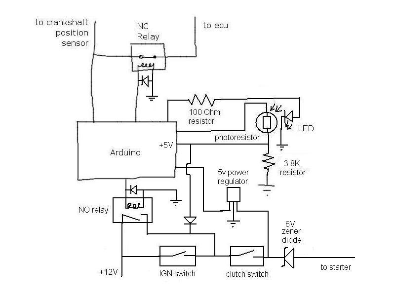
- you plan to measure the shifter is in neutral using the optical feedback using the absense of light to detect if the shifter is blocking the light path. (Note, if there is an issue with the LED or wiring the system will think you are always in neutral)
- you will turn the engine off by opening the NC (normally closed) contact which connects the crankshaft position sensor to the ECU. The ECU will then stop firing the cylinders so engine turns off
- when you shift out of neutral into any other gear you want the system to energize the starter motor. (Note when writing the code you will want to check that the crankshaft position sensor isn't showing any RPM's incase you quickly go in and out of neutral so the engine trys to start the engine even though it is still rotating)
- When the engine is off, if the clutch is depressed you want to have the starter to start immediately while the shifter is still in neutral (or does it matter if the shifter is in neutral or not)
- When starting the motor you will have the starter motor engaged until the you start seeing quick enough crankshaft position sensing changing or RPM of the engine. Alternatively you will have the starter on for a predetermined time say 2 seconds?


So what i am seeing from the assumptions above is that you dont actually need the system to know when the clutch is depressed. This however may cause the code to be changed a bit but here is how i see the code working
- When starting the car in the drive way, The controller is energized when you turn the ignition switch to accessories or on. The controller has the crankshaft position sensor connected to the ECU. The controller checks the crankshaft position sensor, it shows no rpms so it knows the engine is off. The controller then powers the solenoid to bridge the ignition switch. The starter does not start because the clutch is not depressed. The clutch pedal is depressed the RPMs get high enough and the controller denergizes the starter solenoid by denergizing the solenoid across the ignition switch.
- The controller sees that the RPMs are high so the engine is on, the car may be in neutral and if it is and stays in neutral for more than a certain time out the engine is turned off by opening the contact between the crankshaft sensor and the ECU
- The engine is rotating and the controller sees that the RPMs are high, the shifter is put into a gear before the neutral time out and the car is in gear. The controller does nothing other than notes that the state of the shifter is not in neutral.
- The car approaches a stop light, its put into neutral. The controller knows that the shifter was previously not in neutral, it now knows the shifter is in neutral and it knows that the engine is running so it opens the contact between the crankshaft sensor and ECU.
- The engine is reving down. The controller either has a time out then reconnects the crankshaft sensor and ecu or it sees the crankshaft sensor RPM speed reduce to 0 then it reconnects the crankshaft sensor to the ECU. The controller then powers the solenoid that bridges the ignition switch so that as soon as the clutch is depressed the starter will start.
- engine restarting occures by depressing clutch

So if all my assumptions are correct (that is a big if) you will not need to sense when the clutch is connected but you may need to keep your foot down on the clutch long enough for the engine to start.

Now if i am wrong, other ways to measure if the clutch switch is depressed is as follows
- instead of the zener, the regulator and connection to optical circuit you can use other inputs on the arduino. Place say 2 by 100k ohm resistors, 1 across the ignition switch and one across the clutch switch. Then have an input from each side of the clutch switch go into the arduino (making sure you have an appropriate resistive divider to take it down to the correct voltage for inputs to the arduino). If the clutch switch is closed the voltage on both sides of the clutch switch will be the same either 12v or 0v depending on the state of the starter motor and the ignition switch. If the voltages across the clutch switch are different 12v or 0v then the clutch switch is open. Note: this relies on the resistance of the starter coil being low. also you may have issues with either system when the clutch or ignition switch disengage due to voltage spikes

I believe with the existing schematic you have placed above that the 5v reg will blow up because the resistance of the starter will be relatively low with respect to ground so either the 5v reg wont be able to maintain 5v or the solenoid will energize or you may be lucky and it will be just at the right voltage where not much current is taken and there isn't enough energy to close the starter.


Sorry for the long reply but hopefully this gives you a few options and im sure there are a few typo's up there

Also thanks for sending me a pm, i am not often on ecomodder at the moment so if you do want me to reply please send me a pm so i catch the post.

good luck
  Reply With Quote
The Following User Says Thank You to saand For This Useful Post:
Daox (03-18-2011)
Old 03-18-2011, 10:35 AM   #26 (permalink)
Administrator
 
Daox's Avatar
 
Join Date: Dec 2007
Location: Germantown, WI
Posts: 11,203

CM400E - '81 Honda CM400E
90 day: 51.49 mpg (US)

Daox's Grey Prius - '04 Toyota Prius
Team Toyota
90 day: 49.53 mpg (US)

Daox's Insight - '00 Honda Insight
90 day: 64.33 mpg (US)

Swarthy - '14 Mitsubishi Mirage DE
Mitsubishi
90 day: 56.69 mpg (US)

Daox's Volt - '13 Chevrolet Volt
Thanks: 2,501
Thanked 2,586 Times in 1,554 Posts
I'll have to think about it a bit. But, I think you're right. I shouldn't need to monitor the clutch position since it needs to be down in order for the car to start anyways (I don't have a bypass around it nor do I want to add one). I will probably need to adjust my program a bit to account for this, but it should work better this way. Thanks!
__________________
Current project: A better alternator delete
  Reply With Quote
Old 03-18-2011, 11:01 AM   #27 (permalink)
Administrator
 
Daox's Avatar
 
Join Date: Dec 2007
Location: Germantown, WI
Posts: 11,203

CM400E - '81 Honda CM400E
90 day: 51.49 mpg (US)

Daox's Grey Prius - '04 Toyota Prius
Team Toyota
90 day: 49.53 mpg (US)

Daox's Insight - '00 Honda Insight
90 day: 64.33 mpg (US)

Swarthy - '14 Mitsubishi Mirage DE
Mitsubishi
90 day: 56.69 mpg (US)

Daox's Volt - '13 Chevrolet Volt
Thanks: 2,501
Thanked 2,586 Times in 1,554 Posts
I am also going to have to use a beefier relay to bypass the IGN switch. I don't know of any relay that the arduino can power that will handle the amperage spike. The IGN relay is only powering up the starter solenoid, not the starter itself. So, it doesn't have to handle 100+ amps. I figure a normal 30A automotive relay should work fine, and I'll power up the relay coil with a mosfet.
__________________
Current project: A better alternator delete
  Reply With Quote
Old 03-18-2011, 11:12 AM   #28 (permalink)
Wiki Writer
 
Join Date: Jul 2010
Location: Melbourne, Australia
Posts: 236

bugler - '91 Mazda 626
90 day: 35.89 mpg (US)
Thanks: 15
Thanked 25 Times in 22 Posts
sounds good, also a standard transistor bjt should give you enough current to switch the solenoid, these are often cheaper and easier to get compared to mosfets that will activate off 5v or 3v3. so something like a bc546 or similar device which you should be able to get from any electronics shop.
  Reply With Quote
Old 03-18-2011, 12:22 PM   #29 (permalink)
Master EcoModder
 
Join Date: Nov 2008
Location: 18603, USA
Posts: 759

The Crimson Crawler - '04 Hyundai Elantra GLS
90 day: 36.71 mpg (US)
Thanks: 221
Thanked 60 Times in 45 Posts
Does the manual tranny have some sort of Park/Neutral position switch that you could just tap off of to know when it's in neutral? I know that autos use it to know when to kick the reverse lights on; I don't know how it's done on a manual due to lack of experience working on them.
  Reply With Quote
Old 03-18-2011, 01:01 PM   #30 (permalink)
Administrator
 
Daox's Avatar
 
Join Date: Dec 2007
Location: Germantown, WI
Posts: 11,203

CM400E - '81 Honda CM400E
90 day: 51.49 mpg (US)

Daox's Grey Prius - '04 Toyota Prius
Team Toyota
90 day: 49.53 mpg (US)

Daox's Insight - '00 Honda Insight
90 day: 64.33 mpg (US)

Swarthy - '14 Mitsubishi Mirage DE
Mitsubishi
90 day: 56.69 mpg (US)

Daox's Volt - '13 Chevrolet Volt
Thanks: 2,501
Thanked 2,586 Times in 1,554 Posts
Unfortunately there is no neutral switch on manual cars, at least not on mine anyway.

__________________
Current project: A better alternator delete
  Reply With Quote
Reply  Post New Thread


Powered by vBulletin® Version 3.8.11
Copyright ©2000 - 2024, vBulletin Solutions Inc.
Content Relevant URLs by vBSEO 3.5.2
All content copyright EcoModder.com