Well it was a busy weekend. I got a lot done, but there is still alot left. Starting to worry about making my April 30th deadline with a working prototype.
I was hoping to get the PCB's on Friday and have the weekend to assemble and test them. Turns out they wont be delivered till today...Great... But that also means that the parts i forgot to order came in yesterday so I will have everything I need to put them together in 1 go.
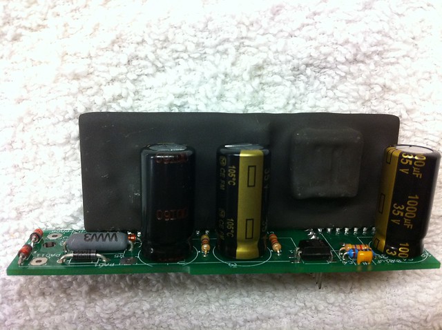
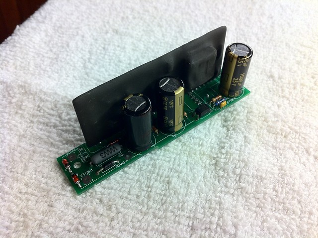
Anyways, I was able to complete the building of the high power driver board. This is the board that uses the VLA-50X modules. Im using a VLA-500 module for now, as it was all I could get my hands on. Mrbigh was kind enough to sell me one of his, as he does not need it before his next order comes in! THANKS A TON!! So I soldered it to the board along with all the supporting passive parts. This board is basically half of the BG2A dev board.
 Untitled
 by
AdamBrunette, on Flickr
 Untitled
 by
AdamBrunette, on Flickr
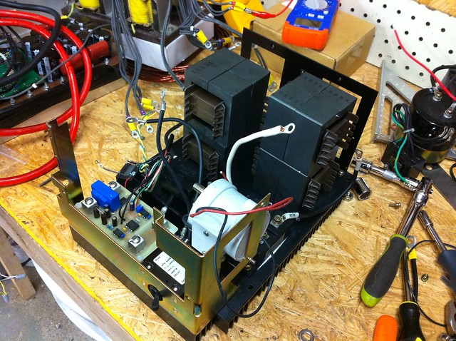
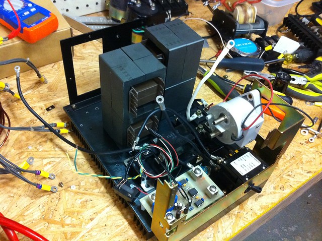
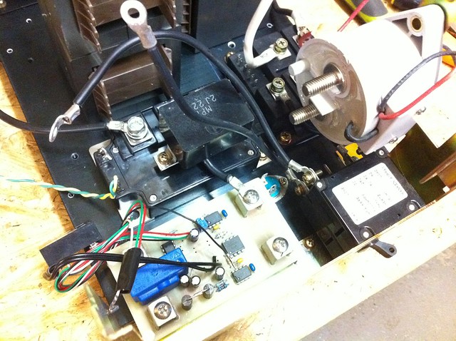
On Sunday I decided to start work on the power section of the charger. My order for high frequency inductor parts came in so I was happy that I could use them during layout of the heat-sink.
I started with the remains of a Yaskawa servo pack for AC servo motors. This was one of the biggest ones I had. It had bad logic, so I didnt feel bad ripping it apart. The drive is from the early 90's. It uses a 60A 3 phase SCR bridge for a rectifier and 3 darlington transistor modules that require 9A base current to turn on!

So I decided to remove them and store them for use probably never. lol I went with a CM400DU-12F Powerex 2-pack IGBT just because I have a bunch of them. 400A is a little overkill. It happend to line up with 2 of the 4 mounting holes of the transistors. I decided to keep the scr bridge for now, and will just turn on the SCR's with the 2V they require and use it as a regular rectifier. The pack would control it to lower the bus voltage. I used 2 AAA batteries before, to activate the scr's when I was playing around build a plasma cutter. It worked well.
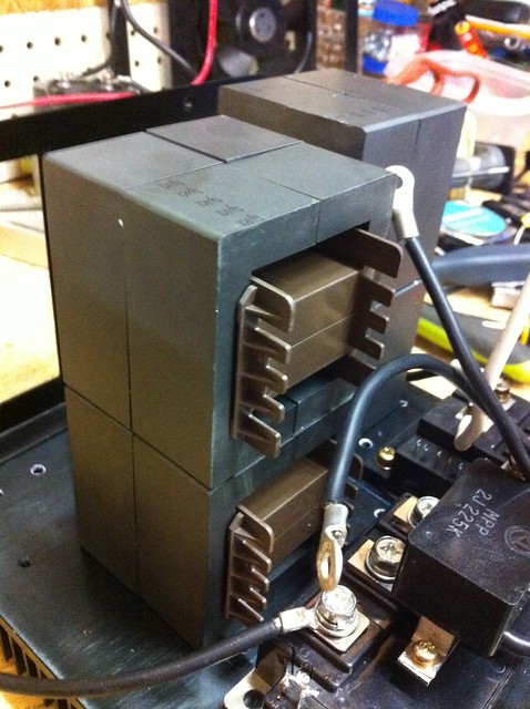
Anyways, I got the IGBT and dc output measurement board mounted as well as the inductors positioned where they will be and brackets designed for mounting them. I also decided to use a Kilovac EV200 contactor for cutting the dc output. Again, I have a few of them, and their really good contactors.
So all thats left is to finish the PFC controller and add bus caps. I plan to use a film cap for the bus cap, as their compact and very powerful. The one im looking at can handle 100A ripple! and its only about $96. Compared to using electrolytic's in 35mm diameter, it would cost about $160. Here are some pics of the power stage.
 Untitled
 by
AdamBrunette, on Flickr
 Untitled
 by
AdamBrunette, on Flickr
 Untitled
 by
AdamBrunette, on Flickr
 Untitled
 by
AdamBrunette, on Flickr
I was also able to test the current capability of the measurement board.
YouTube - DC Measurement Charger Board
Well I think thats it for now. I will post more when Ive got the control board built.
-Adam