|
View Poll Results: What Are You Looking For In A Charger??
|
|
High Power Output / Parallel Operation
|
   
|
24 |
72.73% |
|
Isolated (Narrow Output)
|
   
|
12 |
36.36% |
|
Non-Isolated
|
   
|
6 |
18.18% |
|
Wide Output Range 12-400VDC (No Isolation)
|
   
|
21 |
63.64% |
|
Narrow Range (Built To Suit 1 Voltage Battery Pack
|
   
|
6 |
18.18% |
|
Digital Controls
|
   
|
27 |
81.82% |
|
Analog Controls
|
   
|
8 |
24.24% |
 04-01-2011, 10:39 AM
|
#31 (permalink)
|
|
Master EcoModder
Join Date: Apr 2009
Location: Charlton MA, USA
Posts: 463
Thanks: 31
Thanked 183 Times in 94 Posts
|
Quote:
Originally Posted by jkostec

Adam,
Nice work on the PCB. I used to be in the electronics fab industry. If you are going to assemble these for people and the numbers justify it, you may want to consider ordering a stencil and using solder paste. Even hand soldering becomes much easier. I've ordered 100s, so if you wanted help let me know.
Thanks again for the good work,
John K.
|
Im actually doing that now! lol. I have a friend with a cnc vinyl cutter that I use to make my own stencils out of mylar film. Its great and free. Then pop it into the taster oven in the garage to melt the solder and done with the smd stuff.
If there is enough interest, I will have my friend with the pick and place machines build them in runs.
-Adam
|
|
|

|
 Today Today
|
|
|
|
 Other popular topics in this forum...
|
|
|
|
 04-05-2011, 11:23 AM
|
#32 (permalink)
|
|
ReVolt Enthusiast
Join Date: Jun 2009
Location: Michigan, USA
Posts: 239
Thanks: 97
Thanked 47 Times in 40 Posts
|
6Kw DC Charger Controller on wiki
This project was added to the wiki: Open ReVolt - EcoModder
-Mark  |
|
|

|
 04-07-2011, 08:25 AM
|
#33 (permalink)
|
|
Master EcoModder
Join Date: Apr 2009
Location: Charlton MA, USA
Posts: 463
Thanks: 31
Thanked 183 Times in 94 Posts
|
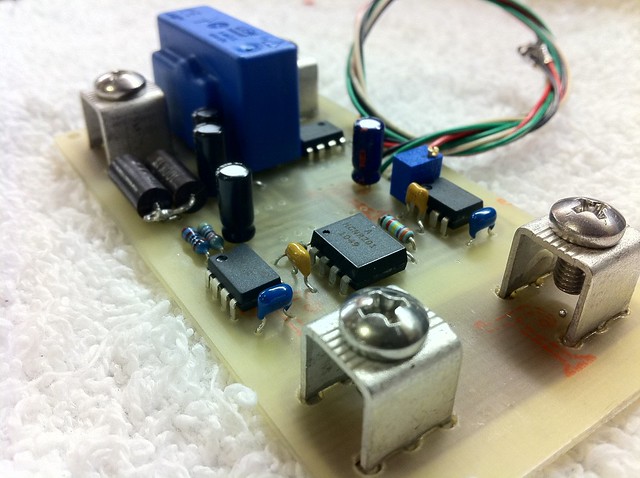
Last night I was able to etch and populate 90% of the board that will be used to measure output of the charger. This board contains a closed loop hall effect sensor thats 0.25% accurate as well as isolated voltage measurement circuit.
My goal with this board is 0-60A and 0-400V all isolated.
The connectors and PCB will be the weak point. However, The circuit board is 5oz and the connectors are meaty. They say they are rated for 30A, but in comparison to other connectors rated to 30A, they are much much heavier. Other connectors have 2 pins that go through the pcb that are the same size as these ones. These have 6 though. Only testing will revele the real current limit.
All thats left to add are the dc-dc converters for isolation that I was not able to afford yet. They are about $15 each... 
Well enjoy!
-Adam
 Untitled
 by AdamBrunette, on Flickr |
|
|

|
|
The Following 2 Users Say Thank You to adamj12b For This Useful Post:
|
|
 04-07-2011, 09:08 AM
|
#34 (permalink)
|
|
ReVolt Enthusiast
Join Date: Jun 2009
Location: Michigan, USA
Posts: 239
Thanks: 97
Thanked 47 Times in 40 Posts
|
Hi Adam,
Thanks for sharing the development of your charger project, It's looking good !!!
Question, how does it all go together? How many modules to make up the complete Charger ? (Controller PCB, Display PCB, Current Sensor PCB, IGBT's ????)
-Mark  |
|
|

|
 04-07-2011, 11:05 AM
|
#35 (permalink)
|
|
Master EcoModder
Join Date: Apr 2009
Location: Charlton MA, USA
Posts: 463
Thanks: 31
Thanked 183 Times in 94 Posts
|
Quote:
Originally Posted by sawickm

Hi Adam,
Thanks for sharing the development of your charger project, It's looking good !!!
Question, how does it all go together? How many modules to make up the complete Charger ? (Controller PCB, Display PCB, Current Sensor PCB, IGBT's ????)
-Mark  |
Hello Mark,
The answer is 3-4 really.
The display and controller are all 1. The driver module plugs onto the back of the controller board. The current/voltage measurement board is connected with a lead cable to the controller board. This is to keep the high power stuff away from the logic a little bit. Thats all thats really needed to make it work. After this, there will be another power board that will have the power factor correction stage on it. Again, optional. Also, there is another optional line sensing board that will measure line voltage and current as well as power factor and other cool stuff. Thats mostly because i like to see everything thats going on. The controller will calculate line current enough to keep it limited from tripping the breaker.
As for the measurement, If you have a full BMS system in the car, that can measure current into the pack and pack voltage, it could be adapted to work off those readings.
So I guess the final answer is anywhere from 2 (controller and driver) up to 5 (Controller, Driver, Current/Voltage Measurement, Line Measurement, and PFC.
-Adam |
|
|

|
 04-12-2011, 11:34 AM
|
#36 (permalink)
|
|
Master EcoModder
Join Date: Apr 2009
Location: Charlton MA, USA
Posts: 463
Thanks: 31
Thanked 183 Times in 94 Posts
|
Well it was a busy weekend. I got a lot done, but there is still alot left. Starting to worry about making my April 30th deadline with a working prototype.
I was hoping to get the PCB's on Friday and have the weekend to assemble and test them. Turns out they wont be delivered till today...Great... But that also means that the parts i forgot to order came in yesterday so I will have everything I need to put them together in 1 go.
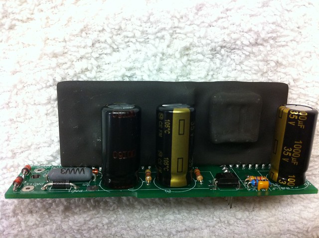
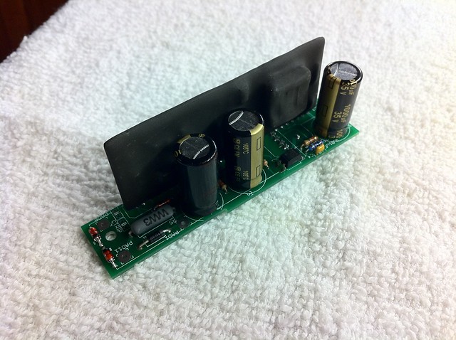
Anyways, I was able to complete the building of the high power driver board. This is the board that uses the VLA-50X modules. Im using a VLA-500 module for now, as it was all I could get my hands on. Mrbigh was kind enough to sell me one of his, as he does not need it before his next order comes in! THANKS A TON!! So I soldered it to the board along with all the supporting passive parts. This board is basically half of the BG2A dev board.
 Untitled
 by AdamBrunette, on Flickr
 Untitled
 by AdamBrunette, on Flickr
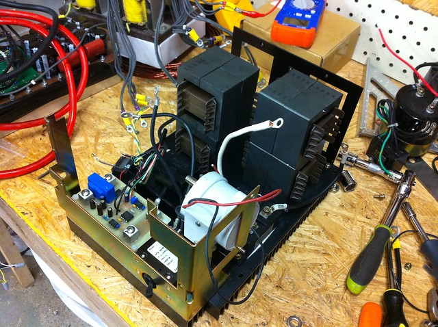
On Sunday I decided to start work on the power section of the charger. My order for high frequency inductor parts came in so I was happy that I could use them during layout of the heat-sink.
I started with the remains of a Yaskawa servo pack for AC servo motors. This was one of the biggest ones I had. It had bad logic, so I didnt feel bad ripping it apart. The drive is from the early 90's. It uses a 60A 3 phase SCR bridge for a rectifier and 3 darlington transistor modules that require 9A base current to turn on!  So I decided to remove them and store them for use probably never. lol I went with a CM400DU-12F Powerex 2-pack IGBT just because I have a bunch of them. 400A is a little overkill. It happend to line up with 2 of the 4 mounting holes of the transistors. I decided to keep the scr bridge for now, and will just turn on the SCR's with the 2V they require and use it as a regular rectifier. The pack would control it to lower the bus voltage. I used 2 AAA batteries before, to activate the scr's when I was playing around build a plasma cutter. It worked well.
Anyways, I got the IGBT and dc output measurement board mounted as well as the inductors positioned where they will be and brackets designed for mounting them. I also decided to use a Kilovac EV200 contactor for cutting the dc output. Again, I have a few of them, and their really good contactors.
So all thats left is to finish the PFC controller and add bus caps. I plan to use a film cap for the bus cap, as their compact and very powerful. The one im looking at can handle 100A ripple! and its only about $96. Compared to using electrolytic's in 35mm diameter, it would cost about $160. Here are some pics of the power stage.
 Untitled
 by AdamBrunette, on Flickr
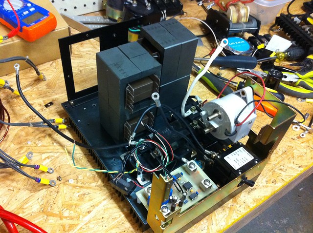 Untitled
 by AdamBrunette, on Flickr
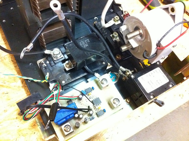 Untitled
 by AdamBrunette, on Flickr
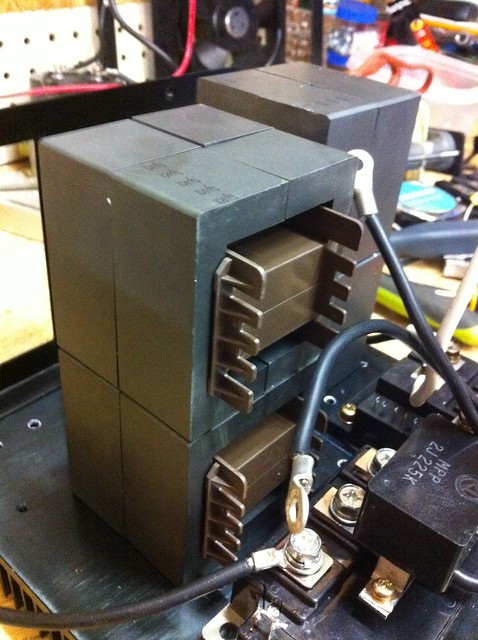 Untitled
 by AdamBrunette, on Flickr
I was also able to test the current capability of the measurement board.
YouTube - DC Measurement Charger Board
Well I think thats it for now. I will post more when Ive got the control board built.
-Adam |
|
|

|
 05-24-2011, 11:10 AM
|
#37 (permalink)
|
|
Master EcoModder
Join Date: Apr 2009
Location: Charlton MA, USA
Posts: 463
Thanks: 31
Thanked 183 Times in 94 Posts
|
Well Its been about a month since the EV show in PA. Ive done a little on the charger but not too much. Will be getting back into it very soon.
A few people have been asking be about a circuit for the power stage. Well here it is.
-Adam
 Charger Power Stage
 by AdamBrunette, on Flickr |
|
|

|
|
The Following 3 Users Say Thank You to adamj12b For This Useful Post:
|
|
 06-25-2011, 08:05 PM
|
#38 (permalink)
|
|
Master EcoModder
Join Date: Nov 2008
Location: Massachusetts, USA
Posts: 442
Thanks: 1
Thanked 60 Times in 45 Posts
|
Hows the charger coming?
|
|
|

|
 06-27-2011, 07:14 AM
|
#39 (permalink)
|
|
Master EcoModder
Join Date: Apr 2009
Location: Charlton MA, USA
Posts: 463
Thanks: 31
Thanked 183 Times in 94 Posts
|
Quote:
Originally Posted by TheSGC

Hows the charger coming?
|
Things have been crazy lately. With the good weather, comes with the honey-do list. Im working on building a deck, a shed and painting the house....busy summer...
I have been working on the PFC section. I recalculated alot of the values for components and think it should work well this time. Just got to get around to testing it.
-Adam |
|
|

|
 10-14-2011, 08:13 PM
|
#40 (permalink)
|
|
AC-DC enthusiast
Join Date: Nov 2009
Location: Long Island, NY
Posts: 282
Thanks: 123
Thanked 54 Times in 37 Posts
|
Quote:
Originally Posted by adamj12b

Things have been crazy lately. With the good weather, comes with the honey-do list. Im working on building a deck, a shed and painting the house....busy summer...
I have been working on the PFC section. I recalculated alot of the values for components and think it should work well this time. Just got to get around to testing it.
-Adam
|
is the desk built and the shed painted yet?
you own us an updqte on the charger
__________________
. .. .. . .... . .... ... ...
Prius Absolutum Dominium . ..........KOPPER
PHEV conversion since Dec 2006.. . .... .Future EV
. . . . . . . .CALCars # 27. . . . . . . . . . ..on the works now !!
. . . . . . . . . . . . . . . . .. . ........
|
|
|

|
|