Pictures of new controller! Holy cow I'm sneaky sometimes...
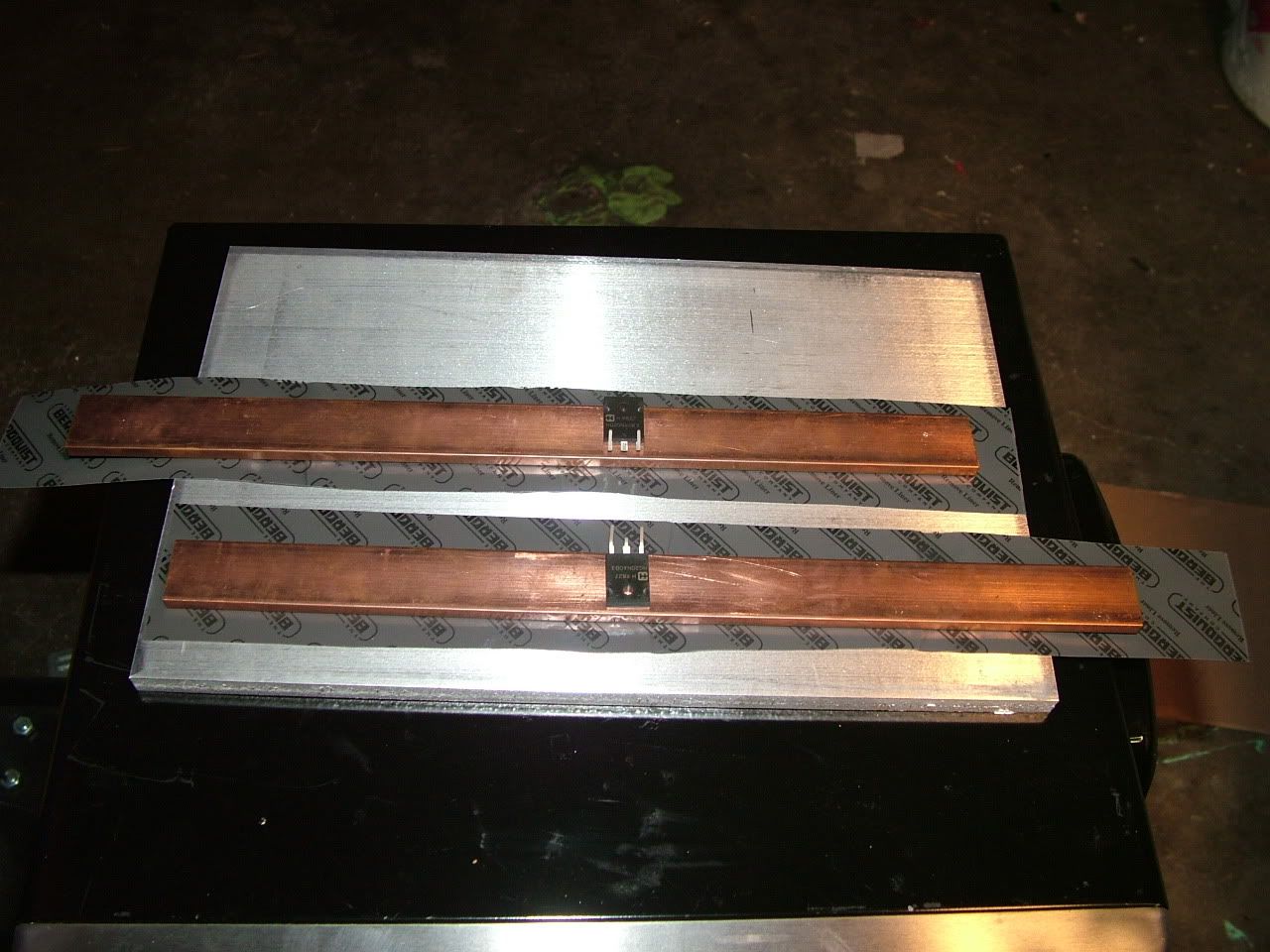
Solder the backs of the mosfets/diodes to the bus bars...
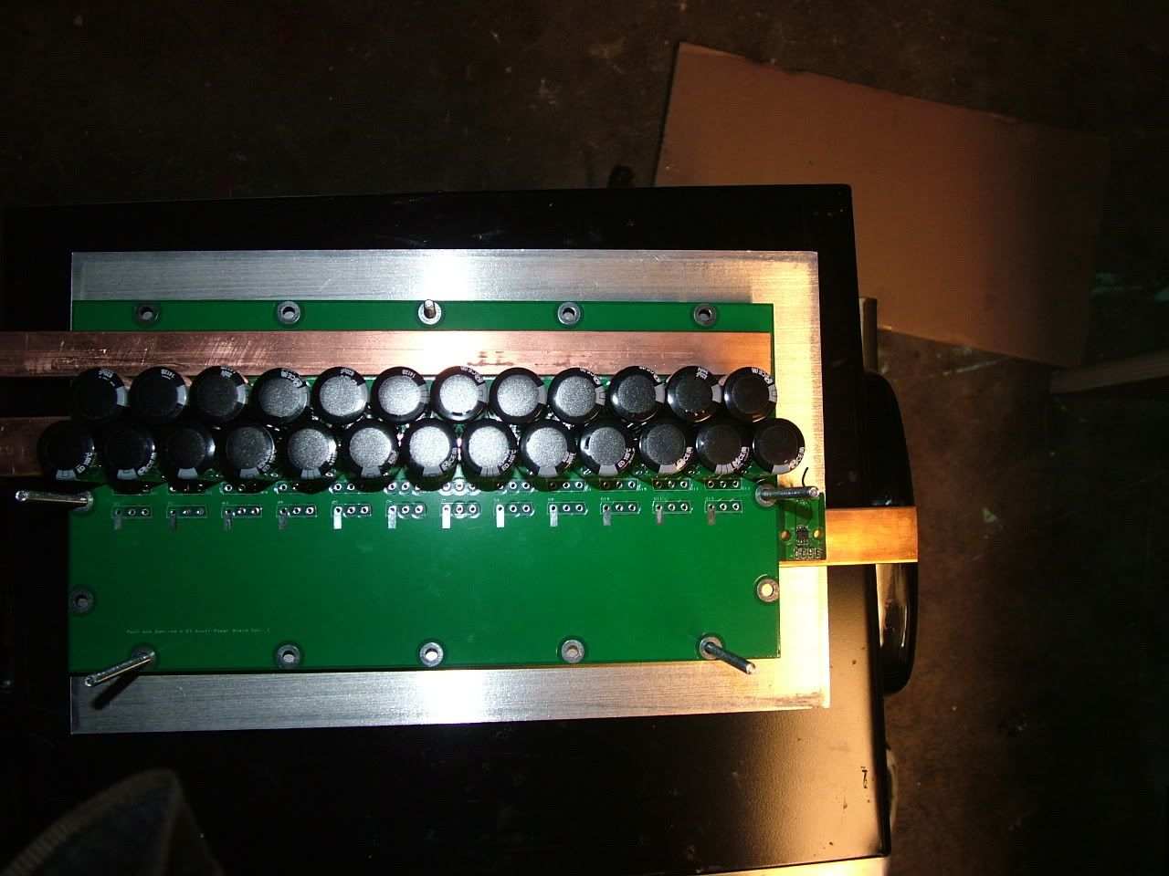
The power board goes on top, and all the mosfet/diode legs go through their respective holes. It's easy to do. Just take the bar with the legs and stick them through! Then flip it upside down! The top bar is B-, and is the only one that is on the power board. I haven't drilled the holes for it yet, but I did write the G-Code for that yesterday:
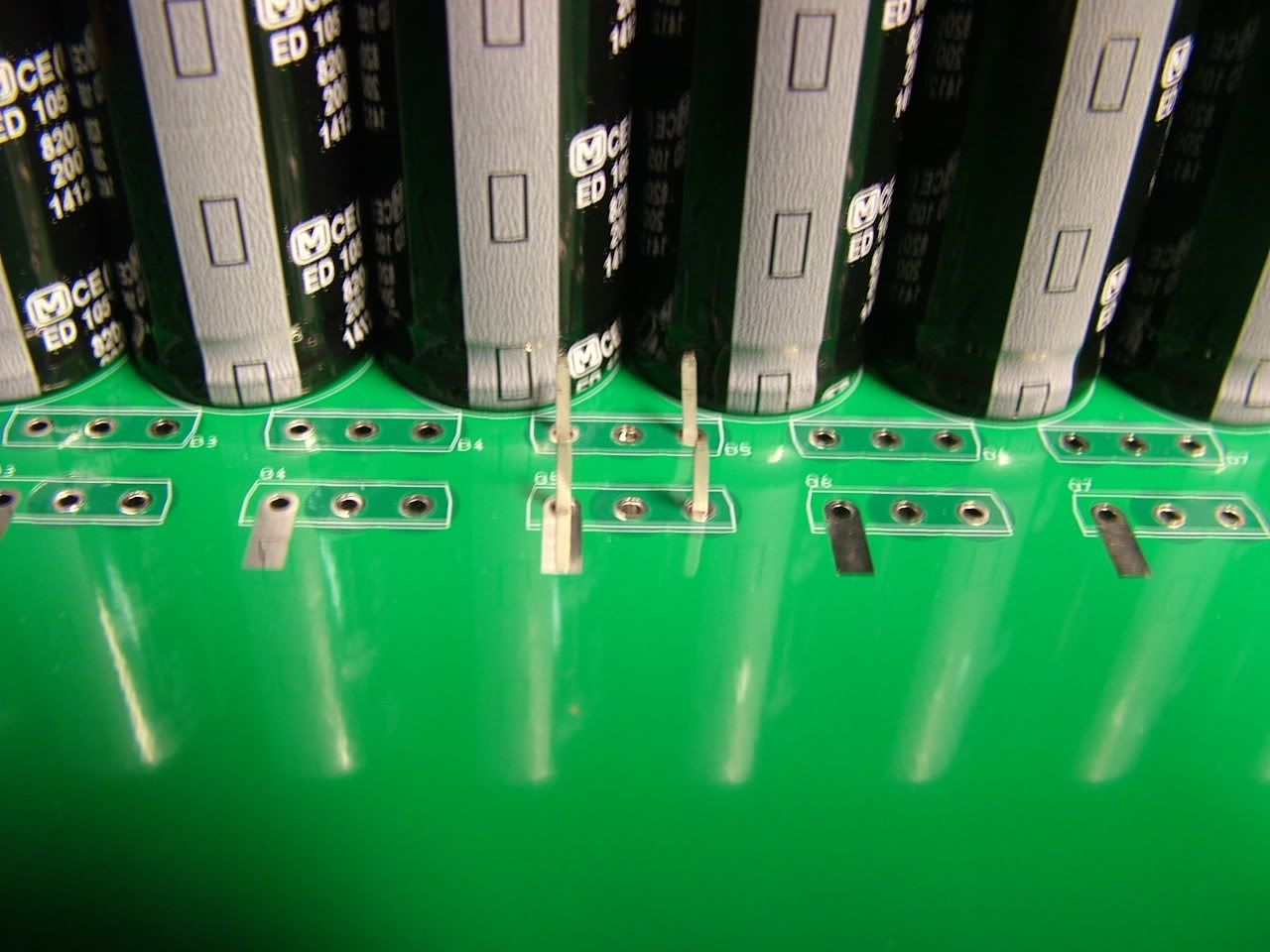
These are just components for practice. See how the legs go through? haha.
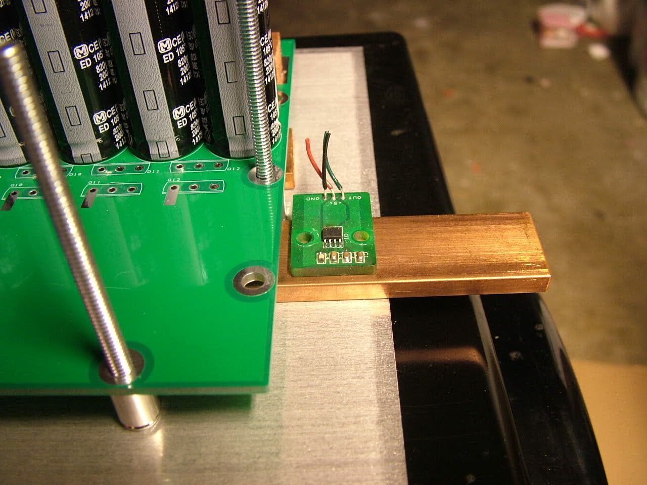
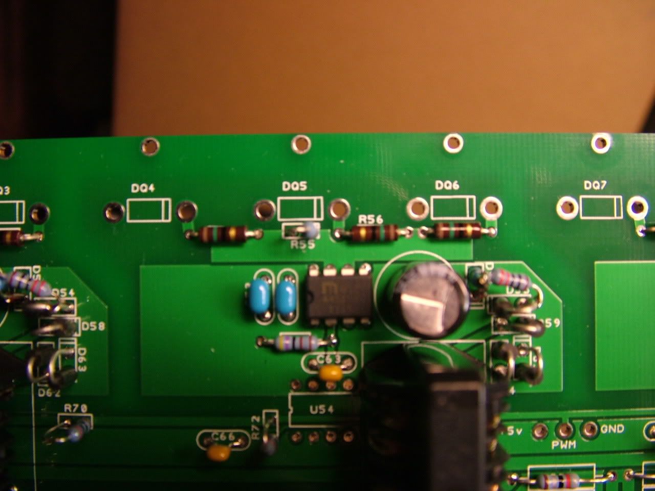
Here's the current sensor board. OK, there's no isolation material underneath now. I admit that!! Back off! Quit picking on me!
Some Silicone that's rated for 500 degF goes on the face of the mosfets and diodes. There's only like 1/20 inch of space, so you can use like 1/16 thick to really squash the bus bars down hard against the base plate. Oops I never got a picture of that part.
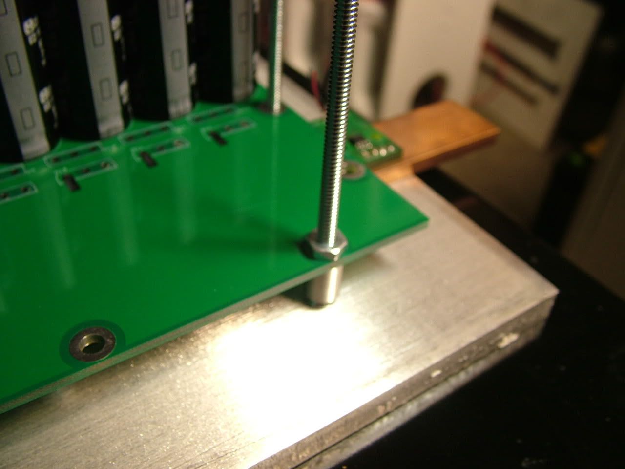
7/32" spacers. Thank you McMaster Carr for all your nonstandard stuff! I got the wrong size screws. A weee bit too long. haha:
4 homemade and CHEAP isolated DC-DC converters! And 4 isolated drivers. Each driver drives 3 mosfets. The bus bar's inductance can cause problems at very high currents with 12 mosfets. So this essentially chops up the bar into 4 little pieces, each with its own isolated supply.
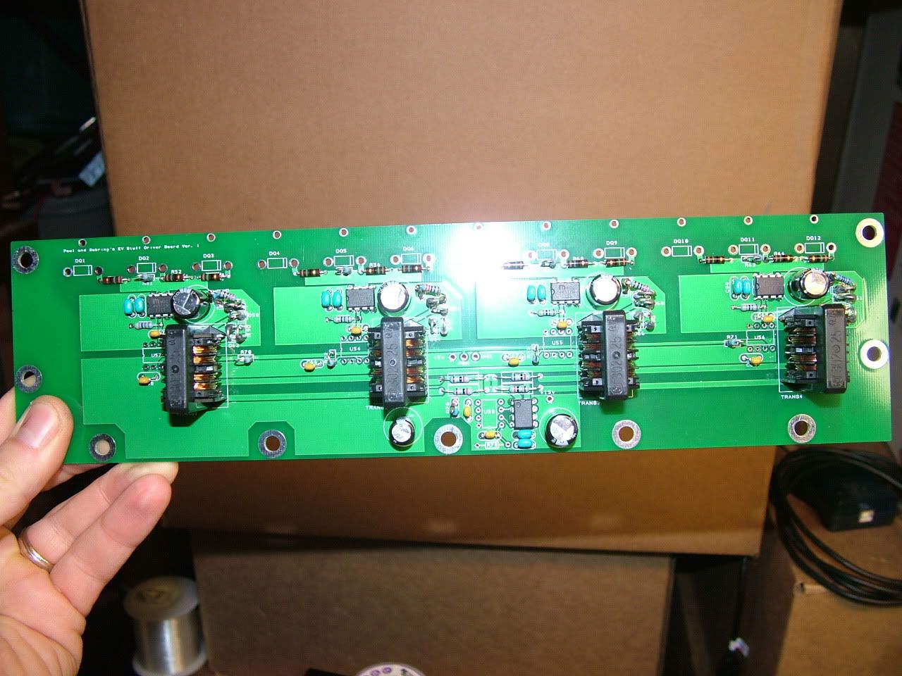
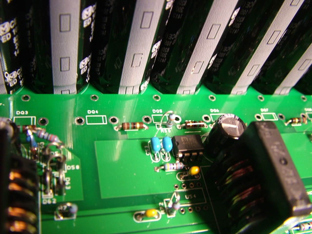
Notice that the distance from mosfet driver output, through resistor to gate leg is essentially identical for all 3. And the legs of the mosfets/diodes stick through both the power board and driver board. They just aren't in this picture. The gate resistors are low inductance "Little Demon" 15 Ohm resistors from Ohmite. Like $0.40 each! man! They come only in 5% tolerance, so I bought 100 of them and matched a group of 12 of them to within about 0.5%. Also notice the "DQ". A TVS diode goes in the hole at the same time as the Mosfet's Gate and Source legs. You can't get any closer than that. haha. I made the hole extra big so the mosfet leg and TVS leg could both fit:
I use some 0.2" thick nuts for spacers between power board and driver board. Nice and close! No more dang blasted wires connecting anything.
The holes close to the capacitors are there in case you want to put a film capacitor from the B+ leg of the diode to the B- leg of the mosfet. You can't get a loop much shorter than that!
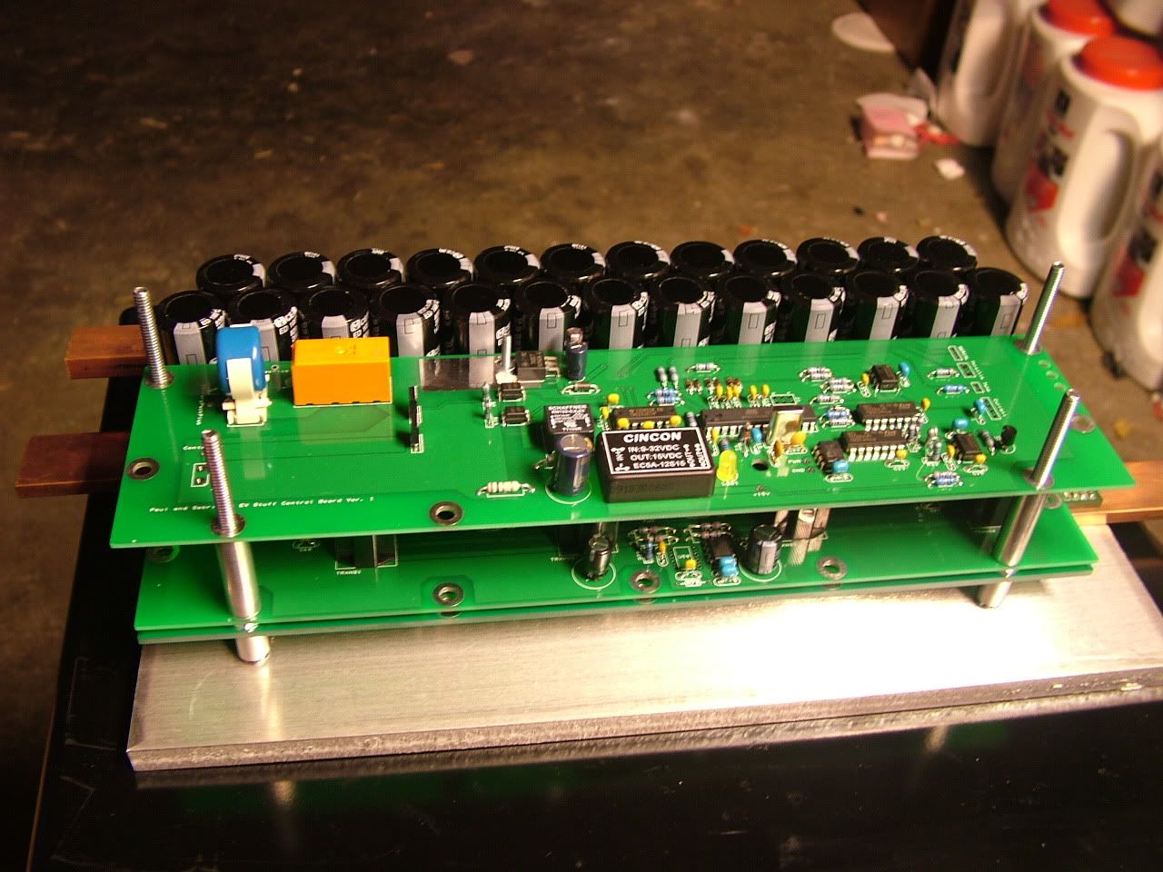
And what's a controller without a control board?! This is just a basic one that I'm pretty sure will work. haha. There's lots of room to add other crap later. It's actually a lot cheaper to do it this way than to make a board as small as possible and then make a mounting board.
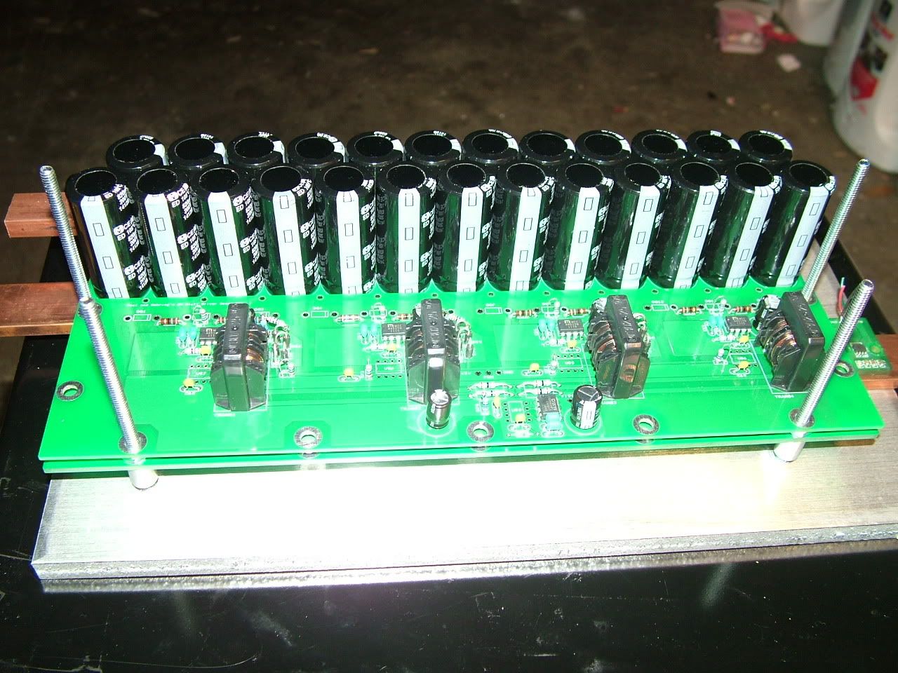
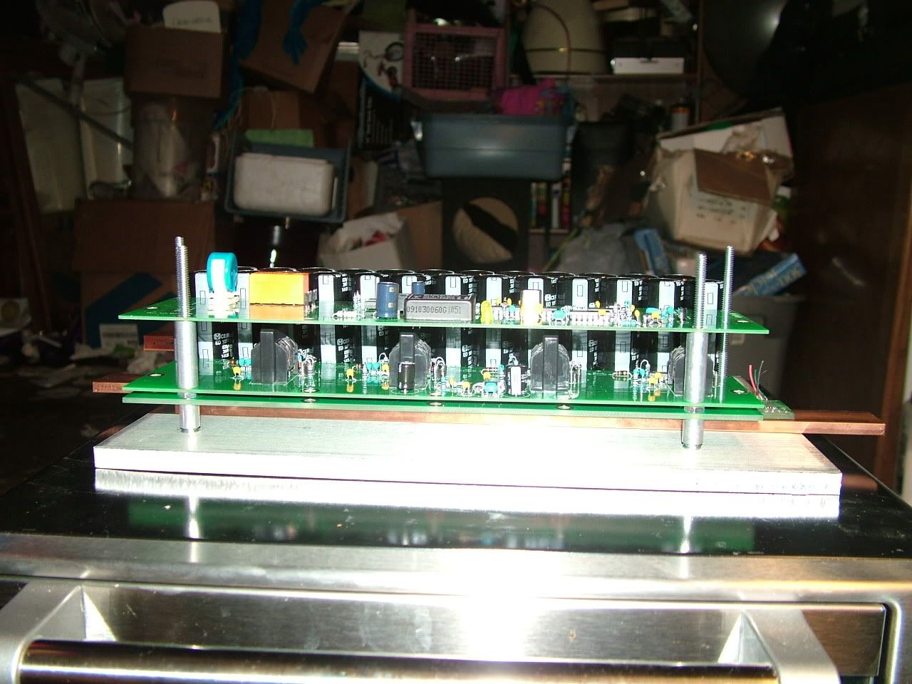
Here's a side view.
I don't ask for much! Please work!!! hahaha