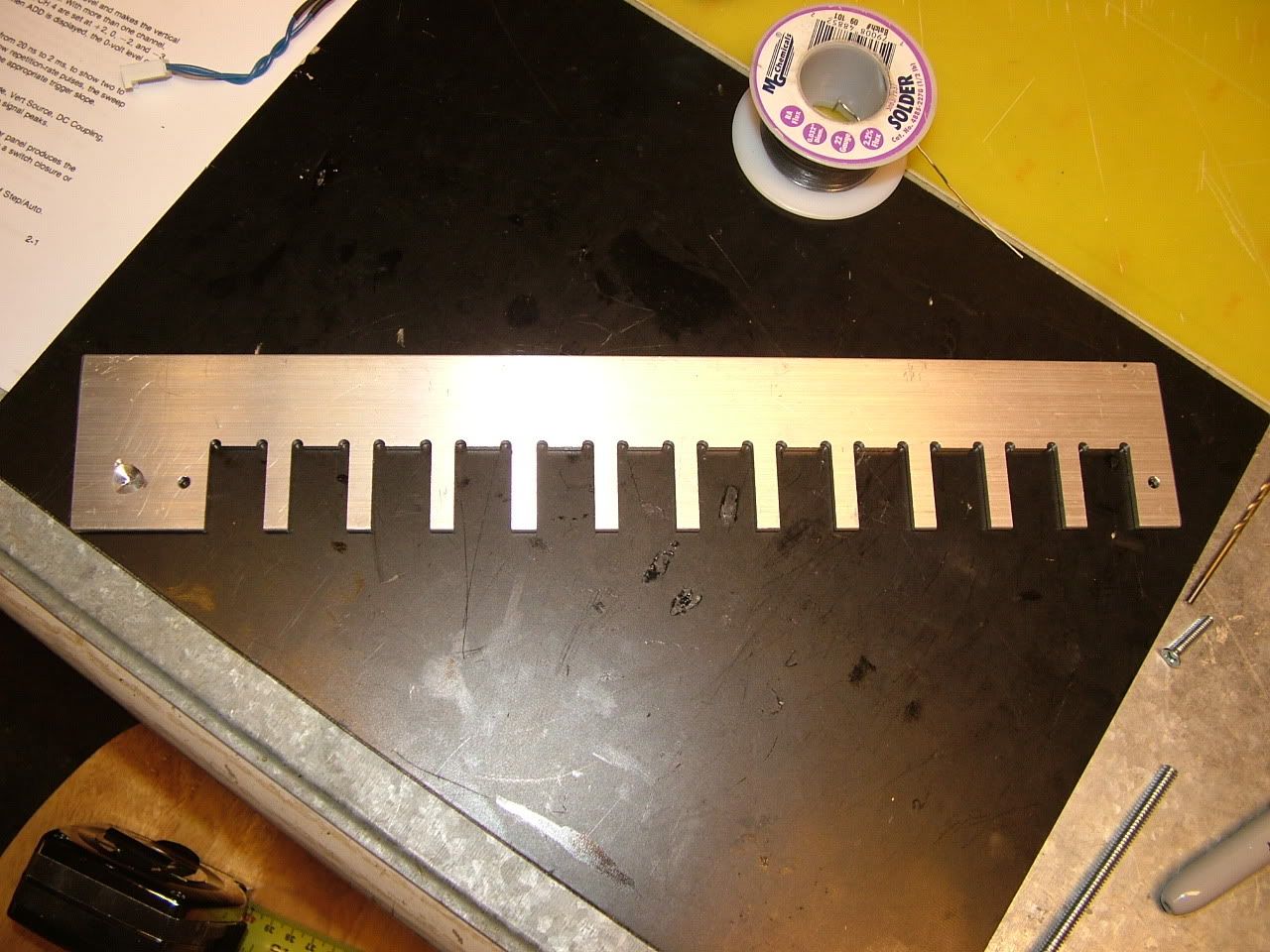
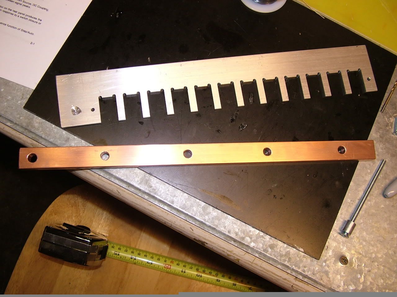
I got the aluminum fixture milled. There's about 0.005" of space for sliding in the mosfets and diodes, so that will be good! The divot there on one end is to set the little piece of solder into. That way the stupid solder won't roll off. haha. Man that's annoying. It's close to the bolt so the aluminum bar is essentially the same temperature as the copper bar. So when that dang solder nugget melts, the whole copper bar is officially at solder temperature. It takes like 8 friggen minutes at 500 degF for the bus bar to get to 180 degC (solder temperature). That copper sure can soak up the heat without increasing temperature much.
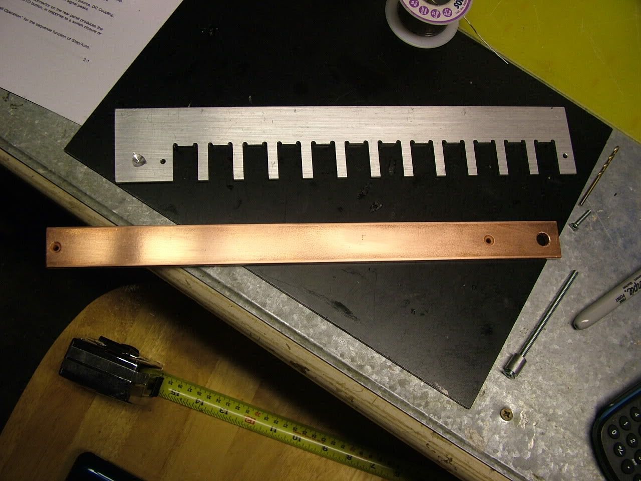
B+ bus bar... Not much drilling, huh! The 2 little holes are for bolting to the aluminum fixture:
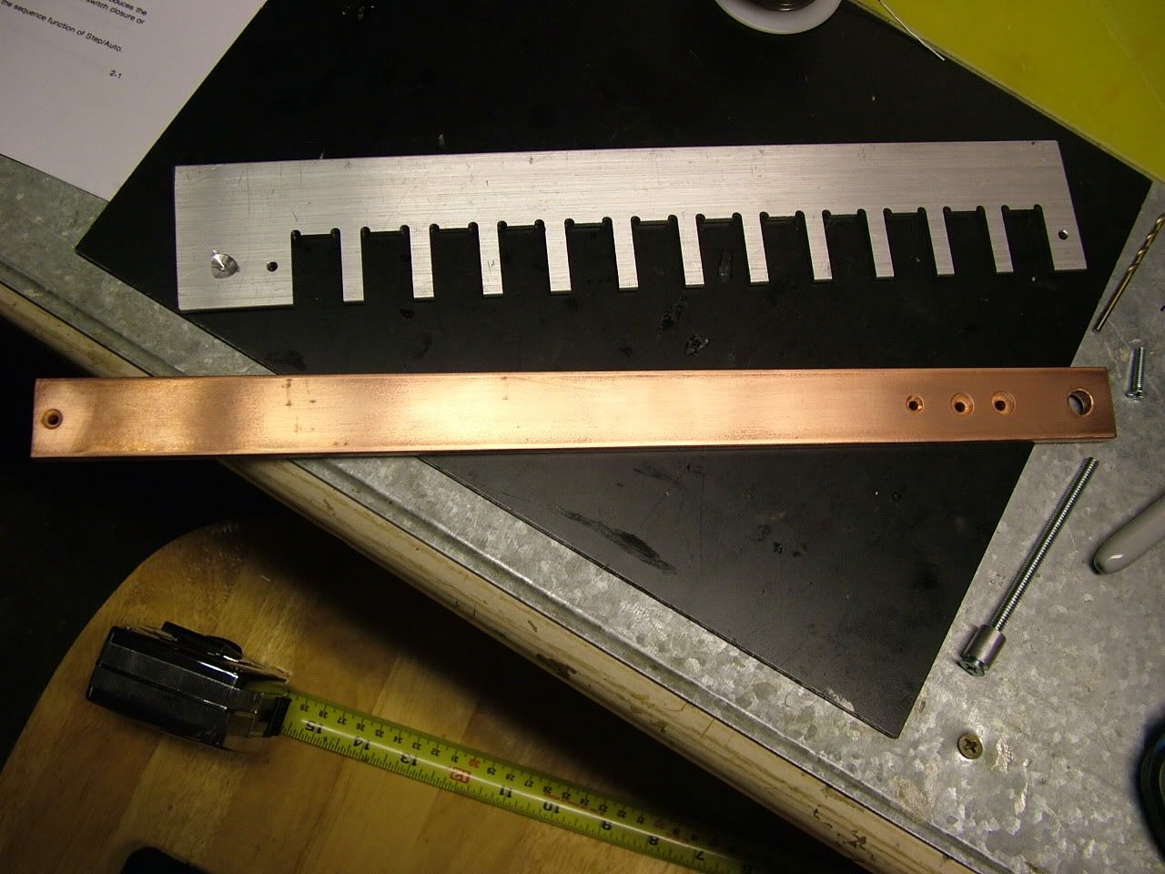
M- bar. 2 holes for bolting to the aluminum fixture, and 2 holes for the current sensor. There's also a hole on the other side that's only part of the way through for the temperature sensor. I'm going to get some good numbers for how long the bar takes to get to a temperature while the mosfets are carying a given current. I only have one temperature sensor on this board, but the next version will have a sensor for the B+ and M- bar:
The B- bar is the only one that gets bolted to the power board. So I need regular old holes for that one, dang it.
Now I just need to drill the base plate, but some of the gcode doesn't exist for it yet. I need some of that friggen $10000 software for modeling things so I don't have to type the stupid gcode!
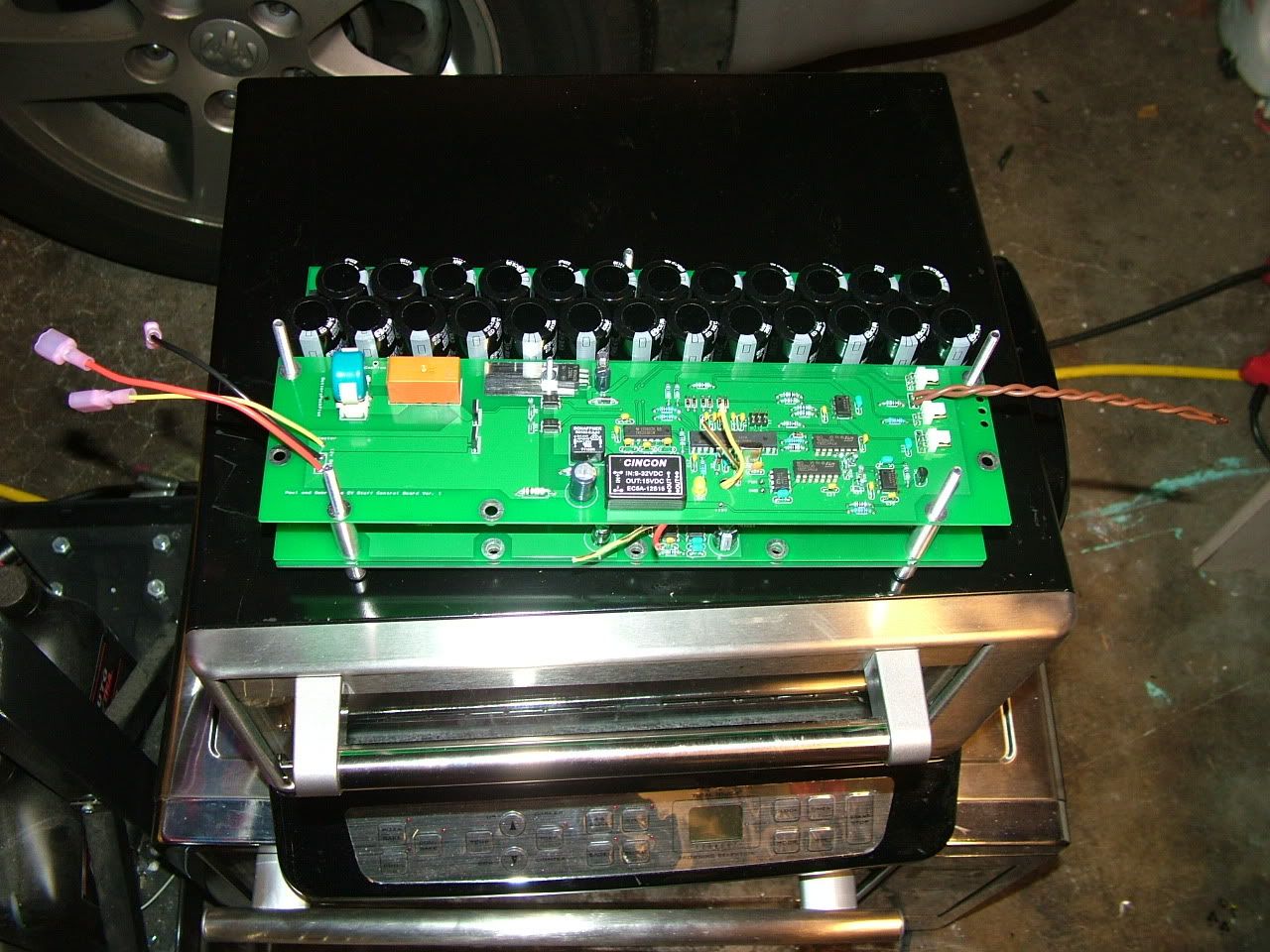
Just about all the wiring is done: