 12-08-2011, 04:51 PM
|
#5261 (permalink)
|
|
PaulH
Join Date: Feb 2008
Location: Maricopa, AZ (sort of. Actually outside of town)
Posts: 3,832
Thanks: 1,362
Thanked 1,202 Times in 765 Posts
|
Notice that U54 isn't in there yet. That's one of the 4 HCPL-4506 optocouplers. The datasheet says that the propagation delay variation from part to part is as much as 500nanoseconds...:
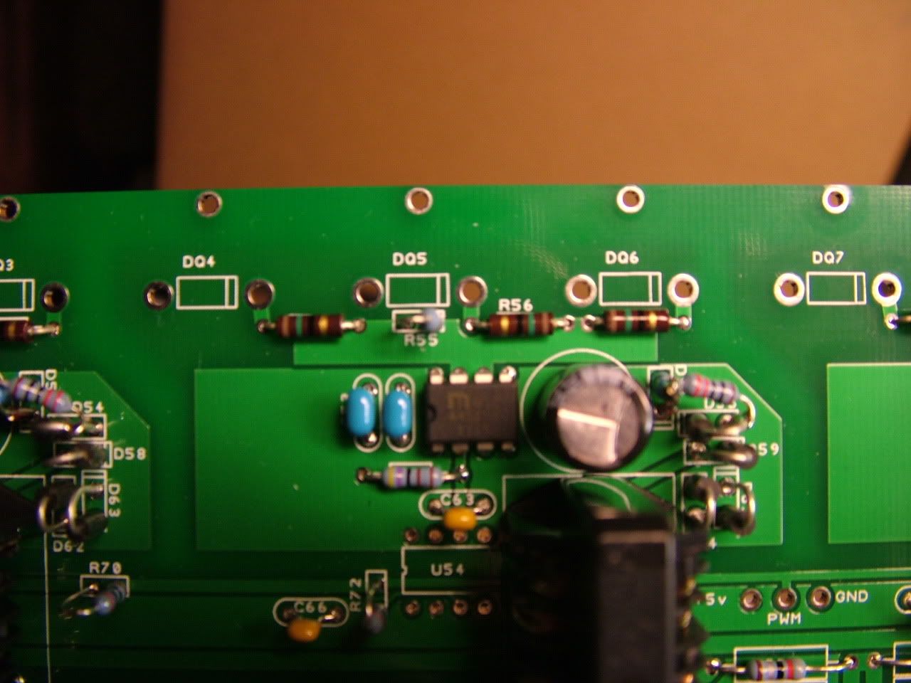
Fran said that it was probably less than that... Well, as usual, he was right, but he didn't realize how right he was:
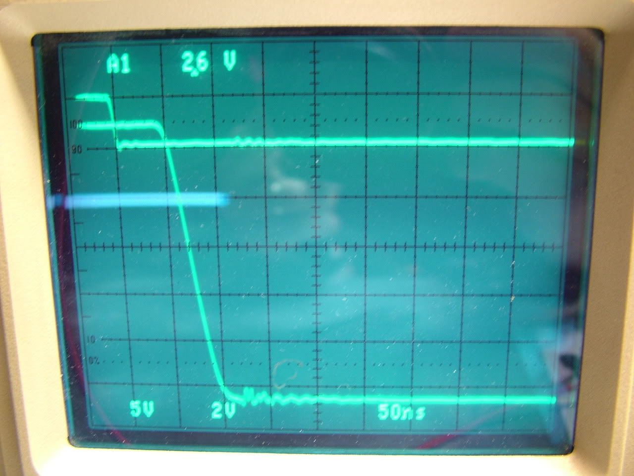
Turn off delay was about 45 nanoseconds before it got the memo to go down.
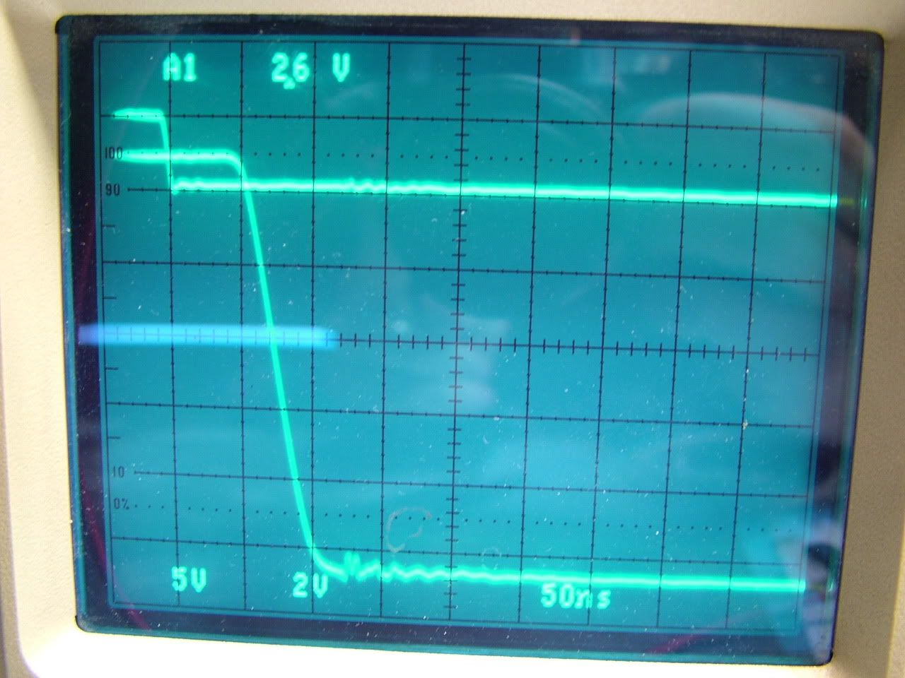
Here's a DIFFERENT hcpl-4506. Maybe a delay of 46? hahaha:
Like 85-90 nanoseconds before it starts to turn on.:
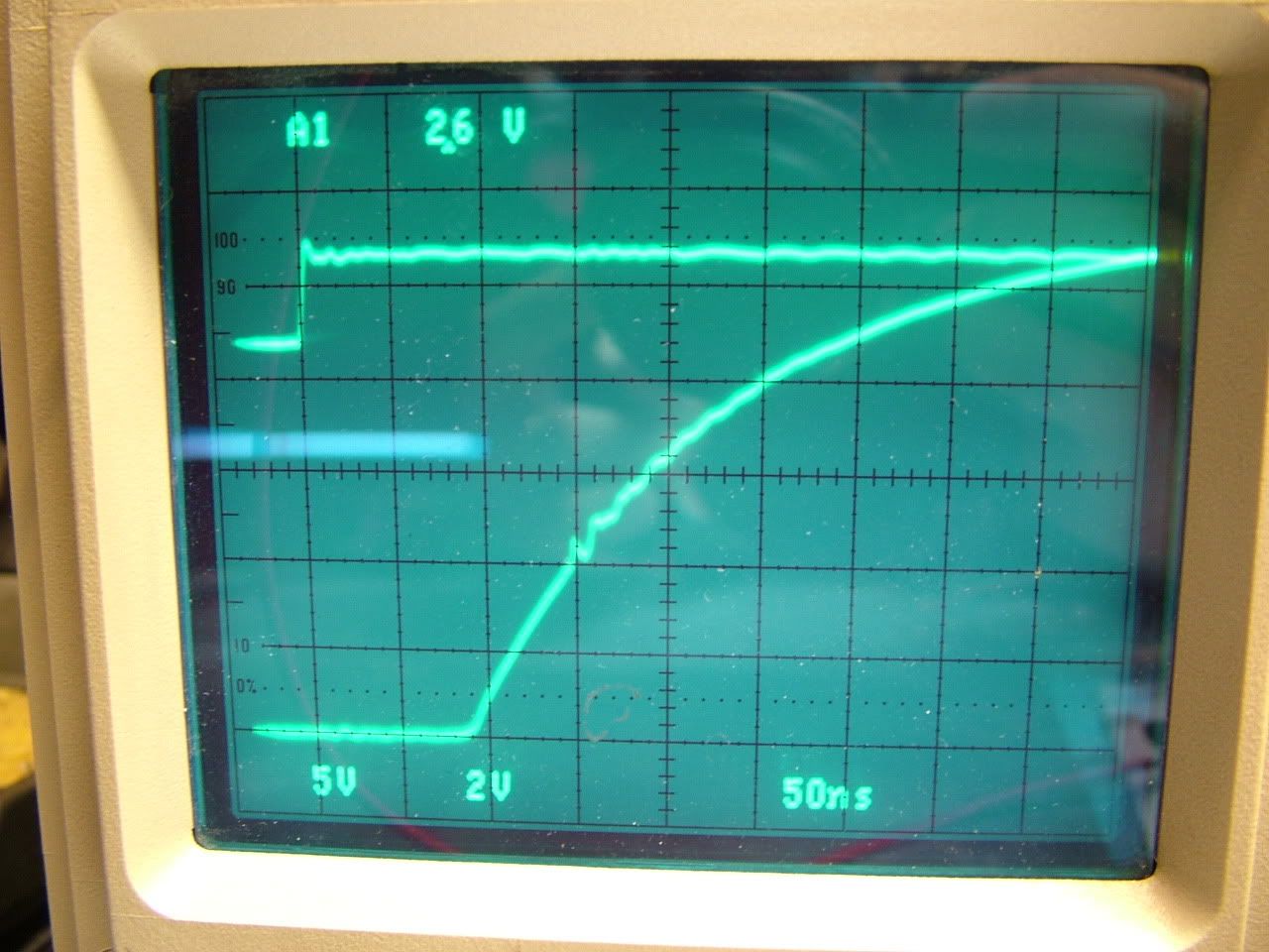
And a different one for turn on:
Man, these things are the same within like 5 nanoseconds or something. That's 5 billionths of a second. I think the mosfets can handle being turned on with a difference of 5 billionths of a second. haha.
Last edited by MPaulHolmes; 12-08-2011 at 07:24 PM..
|
|
|

|
|
The Following 7 Users Say Thank You to MPaulHolmes For This Useful Post:
|
|
 Today Today
|
|
|
|
 Other popular topics in this forum...
|
|
|
|
|
12-08-2011, 05:10 PM
|
#5262 (permalink)
|
|
Master EcoModder
Join Date: Sep 2009
Location: Ireland
Posts: 734
Thanks: 26
Thanked 304 Times in 171 Posts
|
You da man!! 
__________________
Now, Cole, when you shift the gear and that little needle on the ammeter goes into the red and reads 2000 Amps, that's bad.
www.evbmw.com
|
|
|
|
|
12-08-2011, 10:25 PM
|
#5263 (permalink)
|
|
PaulH
Join Date: Feb 2008
Location: Maricopa, AZ (sort of. Actually outside of town)
Posts: 3,832
Thanks: 1,362
Thanked 1,202 Times in 765 Posts
|
The controller is going to be called the "Open Revolt Stinky Diaper". That's because it will hopefully cause the battery pack to gas a lot, which will inevitably lead to other things, including dookies.
|
|
|
|
|
12-09-2011, 10:29 AM
|
#5264 (permalink)
|
|
ReVolt Enthusiast
Join Date: Jun 2009
Location: Michigan, USA
Posts: 239
Thanks: 97
Thanked 47 Times in 40 Posts
|
Quote:
Originally Posted by MPaulHolmes

Does anyone know how to get to the bill of materials for the 2C controller on the wiki?
|
Hi Paul,
Just send to me any files you want to post on the ReVolt wiki.
PM me if you don't have my email address.
I added the Cougar rev2c BOM file that I had to the wiki. Make sure it is correct: http://ecomodder.com/wiki/index.php/...er_.28Rev2C.29
Regards,
-Mark
Last edited by sawickm; 12-09-2011 at 12:06 PM..
|
|
|
|
|
The Following User Says Thank You to sawickm For This Useful Post:
|
|
|
12-09-2011, 04:06 PM
|
#5265 (permalink)
|
|
PaulH
Join Date: Feb 2008
Location: Maricopa, AZ (sort of. Actually outside of town)
Posts: 3,832
Thanks: 1,362
Thanked 1,202 Times in 765 Posts
|
I just checked a breadboarded version of the driver board, with a resistive load on each output which simulated driving a little more than I will actually be doing. The output voltage that the mosfets will see is 13.4 volts. I had been worried that the 4 isolated outputs wouldn't be very similar due to all the parts, but they were the same to better than 0.1%. Not 1% mind you! 0.1%. Oh heck ya.
|
|
|
|
|
12-10-2011, 04:12 PM
|
#5266 (permalink)
|
|
PaulH
Join Date: Feb 2008
Location: Maricopa, AZ (sort of. Actually outside of town)
Posts: 3,832
Thanks: 1,362
Thanked 1,202 Times in 765 Posts
|
I finished the software for the new controller. I'm just compiling it in AVR Studio, which may mean having issues with the bootloader, but for now I'm just going to make changes there. Don't get me wrong... Linux is soon to become the world's dominant operating system due to its ease of use.
|
|
|
|
|
12-11-2011, 03:42 AM
|
#5267 (permalink)
|
|
PaulH
Join Date: Feb 2008
Location: Maricopa, AZ (sort of. Actually outside of town)
Posts: 3,832
Thanks: 1,362
Thanked 1,202 Times in 765 Posts
|
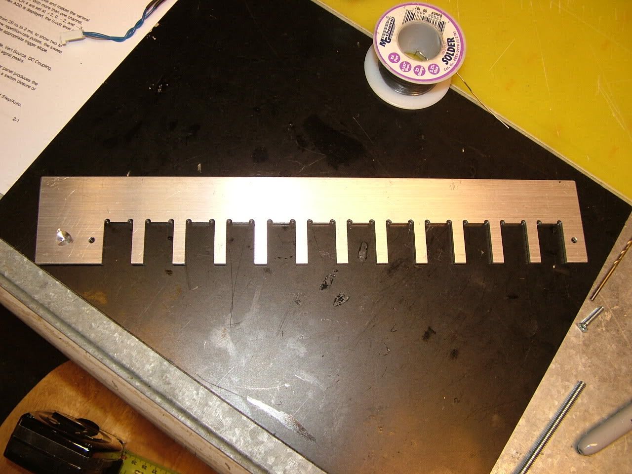
I got the aluminum fixture milled. There's about 0.005" of space for sliding in the mosfets and diodes, so that will be good! The divot there on one end is to set the little piece of solder into. That way the stupid solder won't roll off. haha. Man that's annoying. It's close to the bolt so the aluminum bar is essentially the same temperature as the copper bar. So when that dang solder nugget melts, the whole copper bar is officially at solder temperature. It takes like 8 friggen minutes at 500 degF for the bus bar to get to 180 degC (solder temperature). That copper sure can soak up the heat without increasing temperature much.
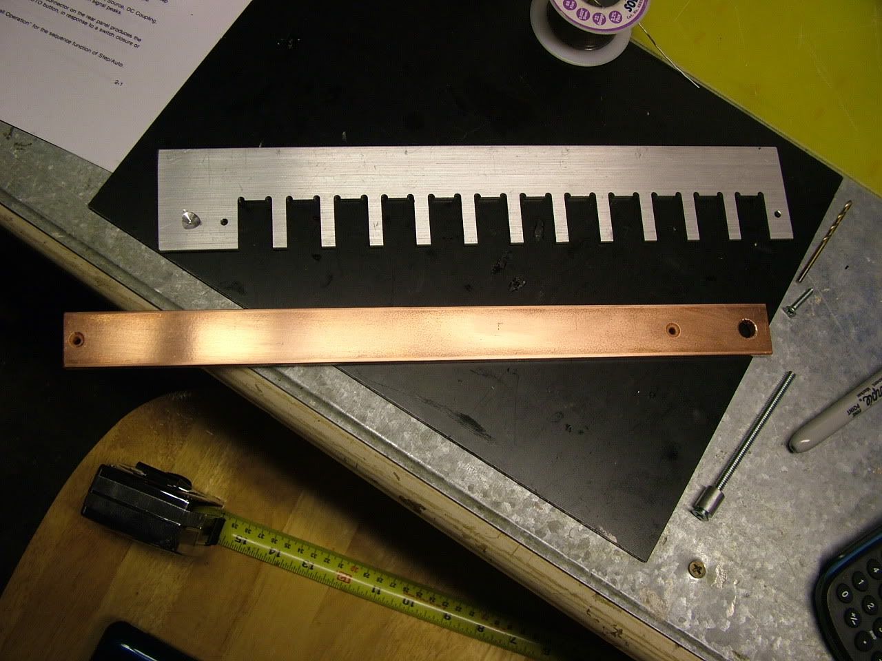
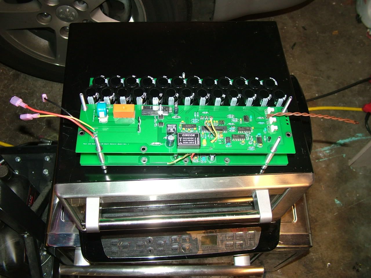
B+ bus bar... Not much drilling, huh! The 2 little holes are for bolting to the aluminum fixture:
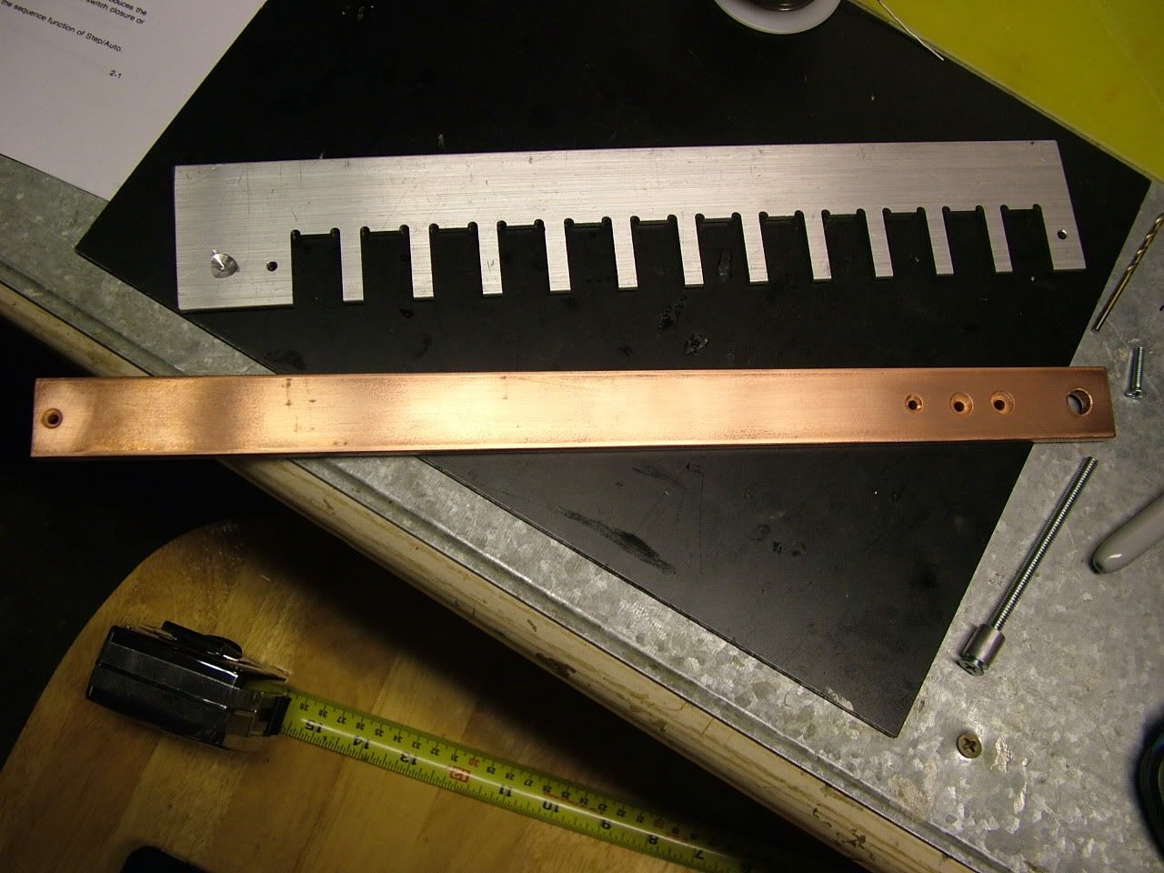
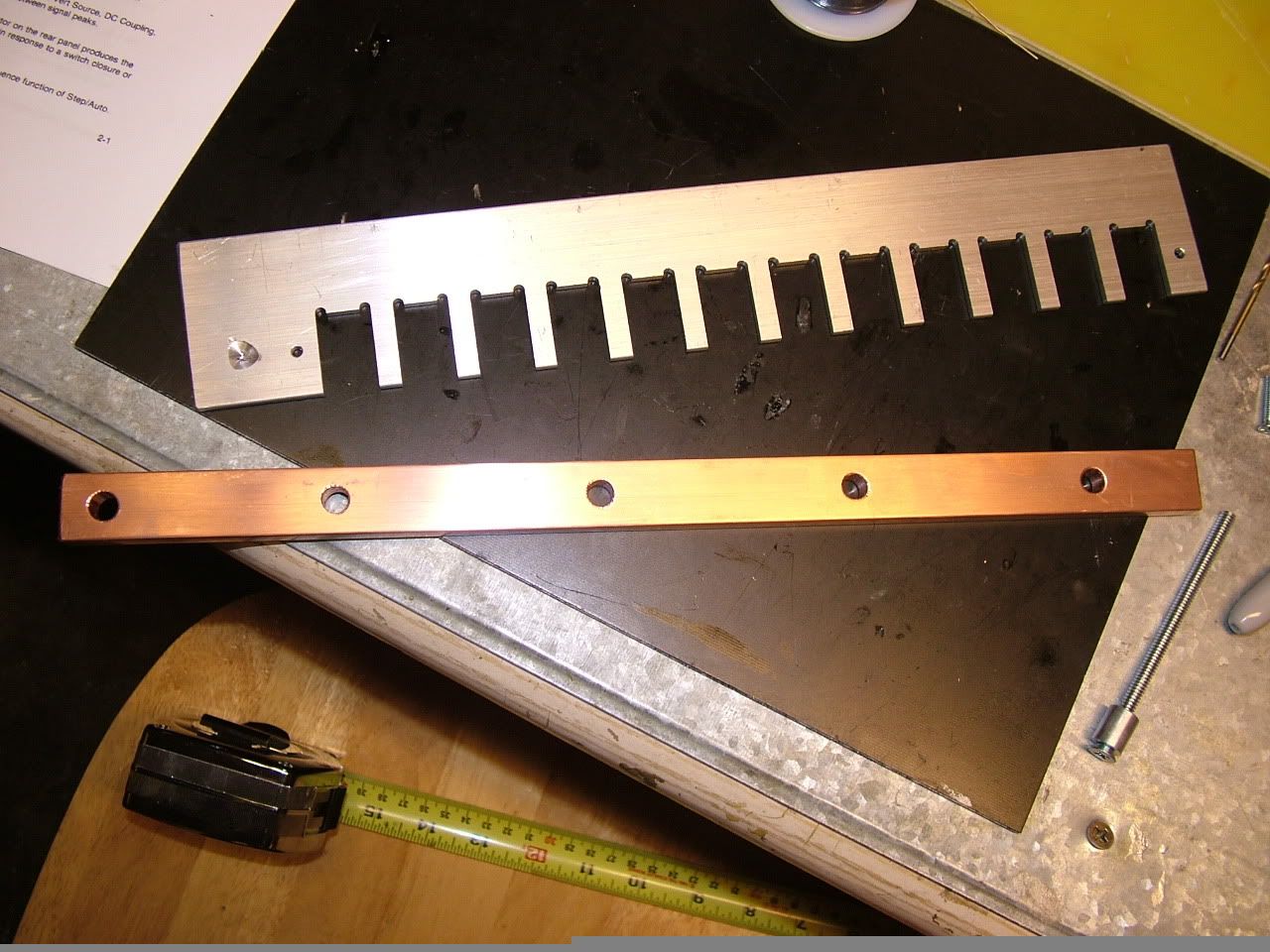
M- bar. 2 holes for bolting to the aluminum fixture, and 2 holes for the current sensor. There's also a hole on the other side that's only part of the way through for the temperature sensor. I'm going to get some good numbers for how long the bar takes to get to a temperature while the mosfets are carying a given current. I only have one temperature sensor on this board, but the next version will have a sensor for the B+ and M- bar:
The B- bar is the only one that gets bolted to the power board. So I need regular old holes for that one, dang it.
Now I just need to drill the base plate, but some of the gcode doesn't exist for it yet. I need some of that friggen $10000 software for modeling things so I don't have to type the stupid gcode!
Just about all the wiring is done:
 |
|
|
|
|
The Following 2 Users Say Thank You to MPaulHolmes For This Useful Post:
|
|
|
12-11-2011, 04:35 AM
|
#5268 (permalink)
|
|
EcoModding Apprentice
Join Date: Oct 2010
Location: southland NZ
Posts: 153
Thanks: 38
Thanked 86 Times in 55 Posts
|
Hi Paul,
I bought a kit from you last Christmas,
excellent kit
I put it together in the winter and now the summer is back I am installing it in my car
The controller will live in the front battery compartment bolted to the side bulkhead,
The heat sink will live in the outside air on the other side of the bulkhead, this should get a fair amount of air flow
The heat sink is four pieces of copper sheet bolted to the aluminium mounting plate bolted in turn to the controller base plate
Anyway some questions
Throttle position sensor
This needs
0 (zero) Ohms for no throttle
5,000 Ohms for full throttle (500 amps)
What happens if it sees more than 5Kohms? does it fault to zero?
How exact does the 5,000 ohms have to be?
My controller has a yellow wire this is for the pre-charge,
Do I connect it to the contactor? or does it need to go through a relay first?
Duncan Cairncross
|
|
|
|
|
12-11-2011, 04:49 AM
|
#5269 (permalink)
|
|
PaulH
Join Date: Feb 2008
Location: Maricopa, AZ (sort of. Actually outside of town)
Posts: 3,832
Thanks: 1,362
Thanked 1,202 Times in 765 Posts
|
Now the summer is back?! It's friggen freezing over here! 
Nice heatsink!
If you go over 5000 Ohms, it just ignores anything beyond it. No biggie. I think about 4500 would be full throttle.
The yellow wire comes disabled. I need to start enabling that sucker. You hook it to the positive of a contactor coil. Make sure you have a diode across the contactor coil to stop the inductive kick from going where it shouldn't. AFter a programmable amount of time, the yellow wire goes from 0v to 12volts. That powers the coil. Program it like this through the serial port:
pc-time XXX
save
Where xxx is a number in tenths of a second. For example:
pc-time 58
save
would cause the controller to wait 5.8 seconds before making the yellow wire go from 0 volts to 12volts. The time you have to wait depends on your precharge resistor value.
You need to wait about 0.1*R seconds, where R is the resistor value. So, if you had a 100 Ohm resistor, you would have to wait 10 seconds. |
|
|
|
|
12-11-2011, 05:28 AM
|
#5270 (permalink)
|
|
EcoModding Apprentice
Join Date: Oct 2010
Location: southland NZ
Posts: 153
Thanks: 38
Thanked 86 Times in 55 Posts
|
Hi Paul,
Thanks for the info
I still have a question (I must be dense today)
If the TPS is over 5000Ohms - does the controller go to zero or max (500 amps)?
I am looking at possible failure modes -
I have a very nice Subaru TPS which has 10KOhms resistance and a nice zero position switch
I was thinking about using a parallel resister to drop it to 5KOhms
i.e. a 10KOhms resister in parallel
One of the possible failure modes would leave 10KOhms - would that be max throttle? or a nice safe - fault - default to zero ?
I'm hoping to get the car rolling over the summer holidays - then I will have to get it certified - then take it to bits to paint it!
(the certifier needs to see the chassis unpainted to check my brazing)
|
|
|
|
|


