Quote:
Originally Posted by AviatorBJP

|
Alright, Im going to chime in now.
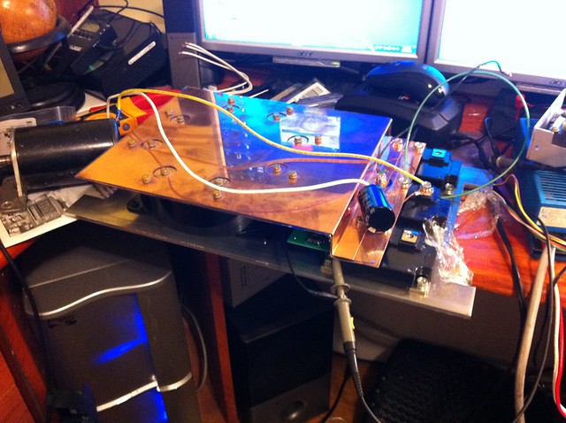
The controller Isaac is talking about, Is my creation. It is a 1000A continuous(still being verified) controller that is built using top quality components. The capacitor is a SBE Power Ring film capacitor that is 1000uF and 600V. At 20kHz, the cap is rated to handle 500Arms all the way up to 70C, and with proper cooling, all the way to 85C. Even at 100C, its still good for about 290A.
The IGBT's are 3 hand matched Powerex CM400DU-12F 400A 600V igbt's. These modules are designed for switching frequencies to about the 20kHz range.
These 3 modules are driven by a driver board designed just for this controller. It uses a Powerex VLA-500 driver module at the heart, and is designed for each gate trace to be minimum inductance and all 3 are identical length. There are provisions for separate turn on and turn off gate resistors to adjust waveform accordingly.
The bus structure is made from 2 plates of 20awg copper that has been waterjet cut and professionally bent to have the proper offset. Between the plates is a piece of CNC cut mylar that is 0.003" thick. This has an isolation rating of about 15kV! Brass bolts and copper washers hold and space everything where it belongs.
Here is the controller during driver testing:
 Untitled
 by
AdamBrunette, on Flickr
The IGBT you picked out, like Isaac mentioned is only the switch. Ideally you should be looking for a half bridge module. This is a module with 2 switches, and each having their own body diode. These modules are common at the junction of Collector of switch 2 and Emitter of switch 1. This allows you to use the C1 terminal as your positive (B+, M+) bus, E2 as your negative (B-) bus and C2E1 terminals as your motor negative (M-).
As for current rating of modules, Its a good idea to stick to 2/3 to 3/4 od the modules current rating as your maximum current. For that module you chose, I would run it in the 400 to 450A range, not exceeding 500A.
The caps might be sufficient but will be run pretty hard. They have a rating of 73Arms @ 55C. With 2 of them, you have about 146A ripple current ability.
Minimally, you should have 25% ripple capacity for the maximum ripple generated. Which occurs around 50% duty cycle. So for a 500A controller, your looking at 125A ripple at 50% duty cycle. That means that your 146A ripple ability could in theory handle a 584A controller.
With 2 of those IGBT's, and 2 of the capacitors, it could be possible to build a controller good to 380-400V and 450A continuous if the bus structure is well planed out. If it is not, you will cause extra heat in the system and have to lower your ceiling.
Hope this helps!
-Adam