I went through the steps that are listed in the instruction in the beginning of the thread and it is not functionally cutting off the alternator. I made a throttle petal controlled delay circuit that disconnects the attached circuit when the throttle is pressed, basically a relay opens and closes a circuit using the gas petal.
I started with it switching power to the alternator fuse (fuse 15) and this worked great. The volts would drop to ~12.5 when the gas petal was pressed. Like others noted this actually kills power to other components so I wired it into the alternator black/yellow wire at the alternator plug. I also clipped the white/blue wire at the connector shown in the picture on page 1. I thought great and tried it out. It seemed to work but I noticed the voltage start to creep up. Giving the engine a little more throttle/rpm it came up to 14.2 when the engine speed increased above 1500rpm. It didn't work.
I tested it going down the highway and it stays solid at 14.2. thinking the circuit was not working I even removed the black/yellow wire extensions and let them dangle in the car open and it still charged.
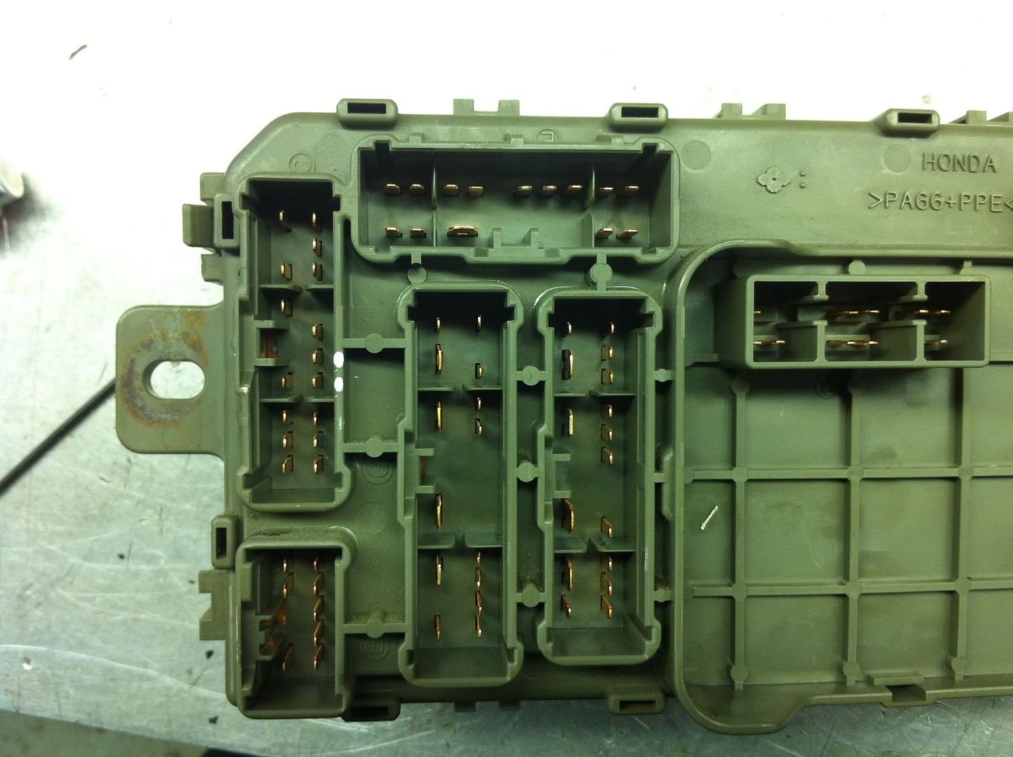
I looked at a wiring diagram to find out what has power when that fuse is in that could be running the alternator. It appeared that the ELD is powered via the same fuse on a different wire (see fig: 1) so I found it. C421 pin12 on the back of the fuse box. I used an OHM meter to verify the pins were connected to the same fuse, #15 (see fig:4). I also OHMed the wires to verify pin13 went to the alternator(see fig:3). I routed the ELD power wire into the circuit also, it only gets power when the throttle is not pressed. After all this the alternator STILL works. I don't see anything else that could be powering the alternator on that circuit. Remember, when I hooked the circuit directly into the fuse it worked, but it's not working attached to the wires shown in the diagrams below.
Any ideas would be greatly appreciated. Thank you in advance.
Fig:1 [red x's show where i have the wires disconnected.]
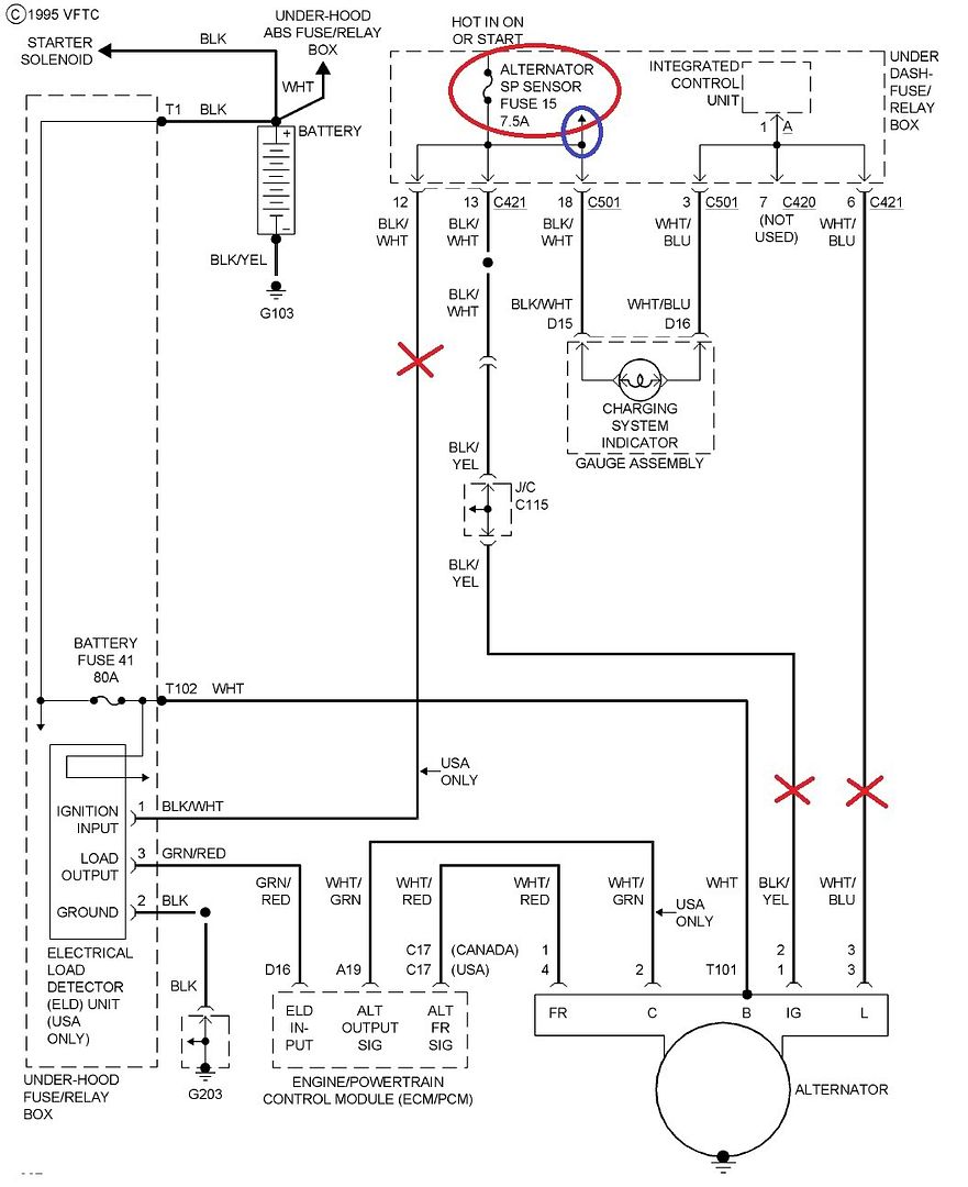
Fig:2 [red x's show where i have the wires disconnected.]
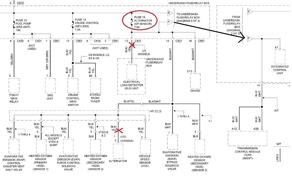
Fig:3 [shows harness side of C421]
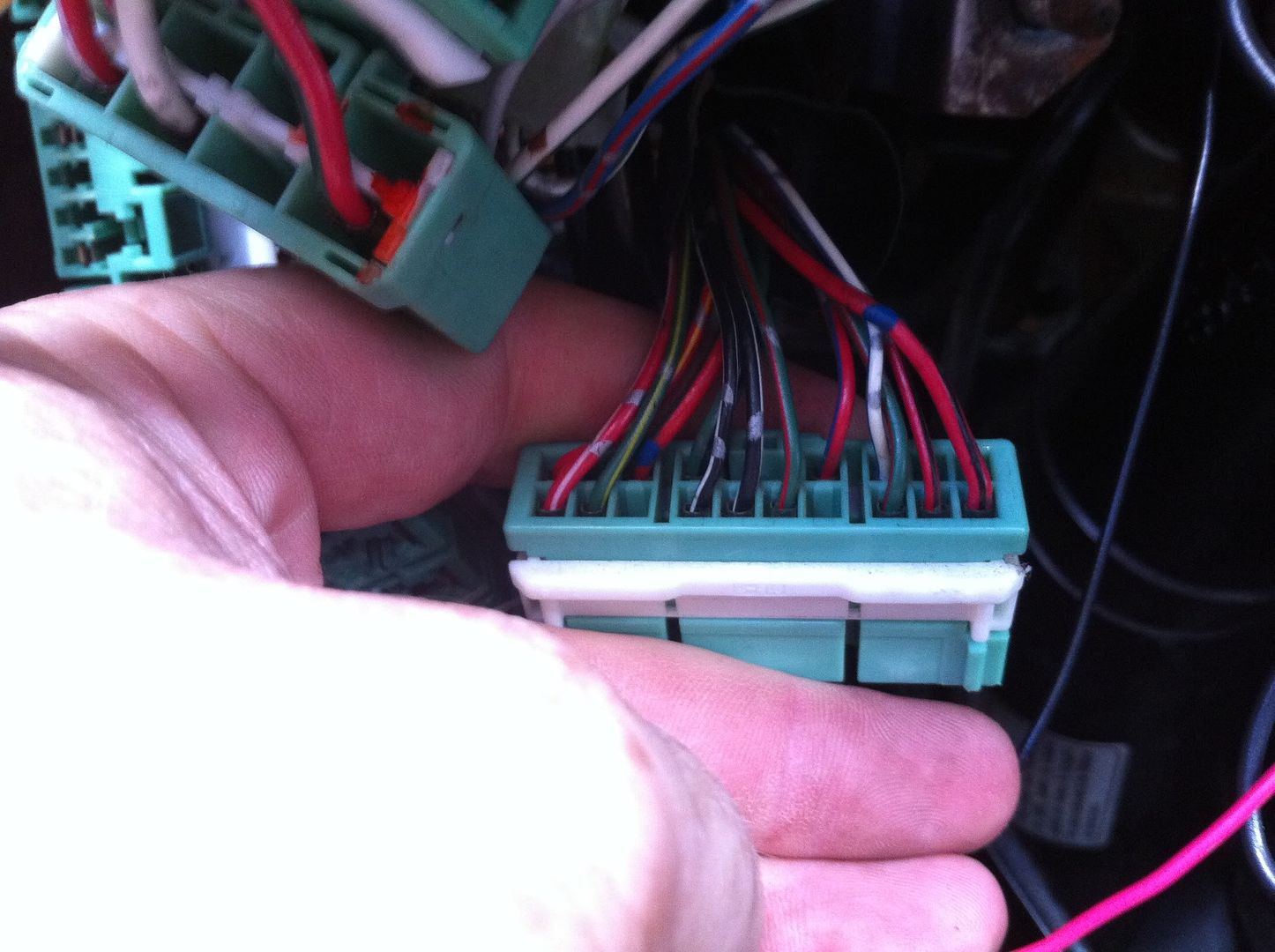
Fig:4 [pin 12 (lower) & pin 13 (upper) marked with white dots]