 04-19-2012, 10:41 AM
|
#41 (permalink)
|
|
Master EcoModder
Join Date: Oct 2009
Location: Midwest
Posts: 337
Thanks: 4
Thanked 37 Times in 21 Posts
|
Quote:
Originally Posted by JanvdW

I thought about a system where I would have a cut-off switch for the alternator, (with a Volt meter to monitor battery power levels)
Then install a floor mounted push-button, on the floor about a foot behind the clutch pedal. If you go down a steep hill, or approach a stop, and use the engine compression to slow down the vehicle in stead of the brakes, you step on the switch, re-engaging the alternator. The alternator will then generate power from the "braking action" and not consume fuel.
You cannot step on it while the clutch is pressed.
--Obviously only applicable to manual transmission vehicles--
(accessories sold separately, batteries not included)
|
Sorry to burst your bubble, but I already thought of this. 
My version is a little better (i think). What you would do is put a micro switch at the end of the gas pedal travel. Whenever the gas pedal is all the way down, you would be coasting to a stop. With this method you don't have to worry about yet another foot pedal/switch, it just simply is connected to an existing one(gas pedal).
You would also want to set up a disable switch on the dash in case you want to charge all the time, and also have a bypass switch on the dash that would ignore the gas pedal micro switch so you never charge.
I might end up doing this, but for now I don't have any deep cycle batteries.
Oh, and honda's ecu actually already does this. When the tps shows its closed the alternator will charge. I don't know how much drag there is, but it is noticable, as you can coast farther with the alternator off, then when its on(i've tested with my current 1 switch alternator disable, flipping it on and off during a highway coastdown).
|
|
|

|
 Today Today
|
|
|
|
 Other popular topics in this forum...
|
|
|
|
 05-01-2012, 05:22 PM
|
#42 (permalink)
|
|
Master EcoModder
Join Date: Oct 2009
Location: Midwest
Posts: 337
Thanks: 4
Thanked 37 Times in 21 Posts
|
This was an interesting read, "If you have an alternator and are using the factory style indicator light on your dashboard, it is a pretty helpful thing. It helps kick-start the alternator into working at idle speeds when you first start the car"
source, Alternator and Generator Theory |
|
|

|
 05-23-2012, 09:16 PM
|
#43 (permalink)
|
|
EcoModding Lurker
Join Date: Jul 2011
Location: Greensboro, MD
Posts: 17
Thanks: 4
Thanked 12 Times in 6 Posts
|
Problems getting generator to not turn on.
I went through the steps that are listed in the instruction in the beginning of the thread and it is not functionally cutting off the alternator. I made a throttle petal controlled delay circuit that disconnects the attached circuit when the throttle is pressed, basically a relay opens and closes a circuit using the gas petal.
I started with it switching power to the alternator fuse (fuse 15) and this worked great. The volts would drop to ~12.5 when the gas petal was pressed. Like others noted this actually kills power to other components so I wired it into the alternator black/yellow wire at the alternator plug. I also clipped the white/blue wire at the connector shown in the picture on page 1. I thought great and tried it out. It seemed to work but I noticed the voltage start to creep up. Giving the engine a little more throttle/rpm it came up to 14.2 when the engine speed increased above 1500rpm. It didn't work.
I tested it going down the highway and it stays solid at 14.2. thinking the circuit was not working I even removed the black/yellow wire extensions and let them dangle in the car open and it still charged.
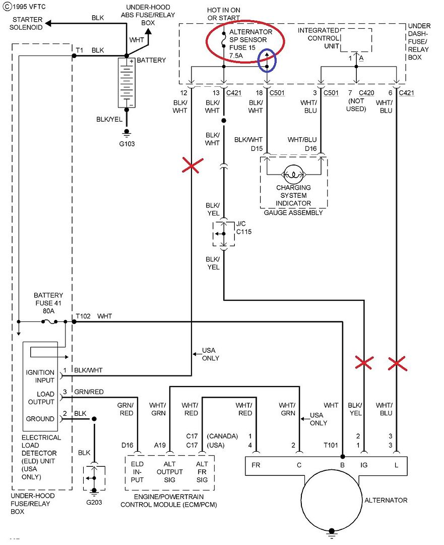
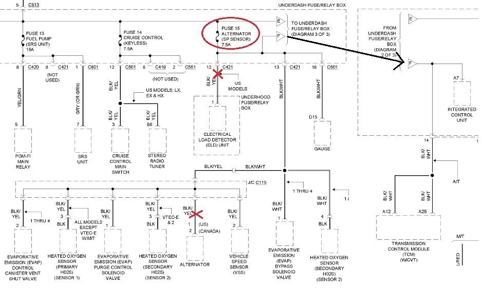
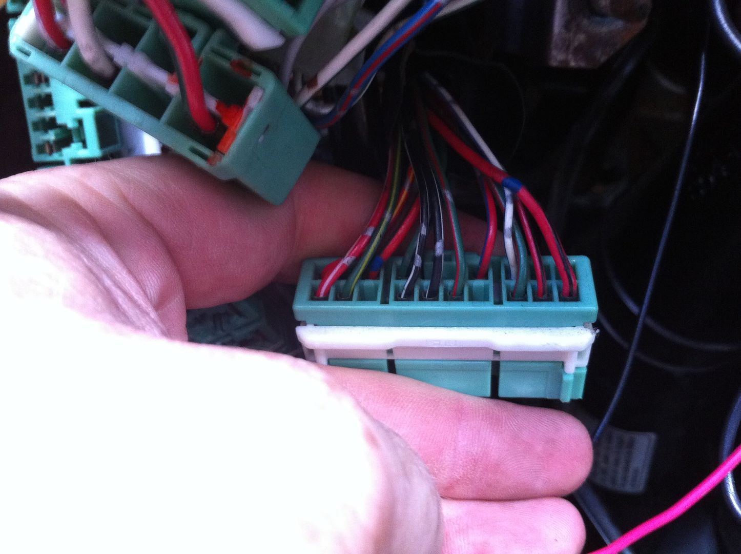
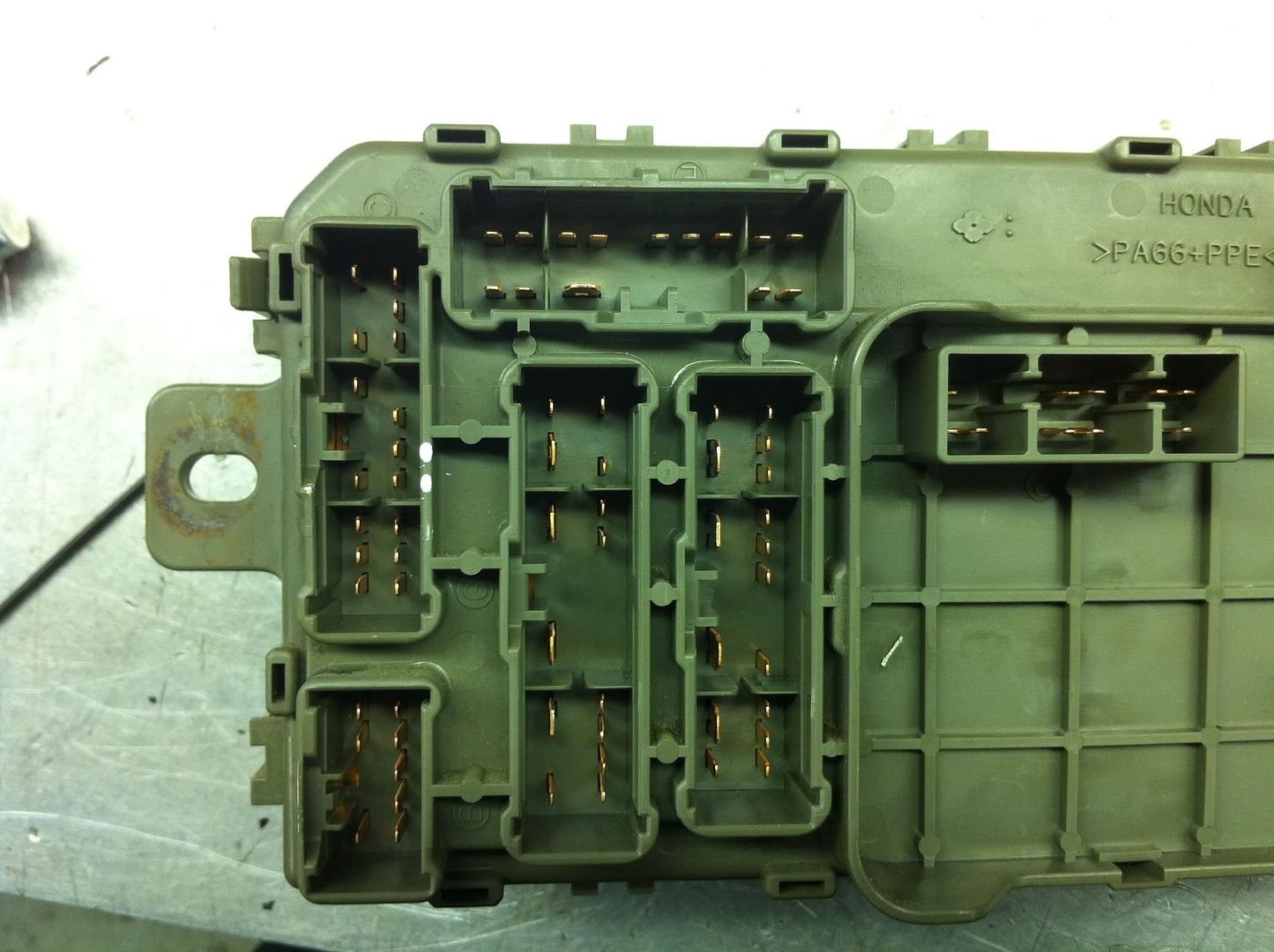
I looked at a wiring diagram to find out what has power when that fuse is in that could be running the alternator. It appeared that the ELD is powered via the same fuse on a different wire (see fig: 1) so I found it. C421 pin12 on the back of the fuse box. I used an OHM meter to verify the pins were connected to the same fuse, #15 (see fig:4). I also OHMed the wires to verify pin13 went to the alternator(see fig:3). I routed the ELD power wire into the circuit also, it only gets power when the throttle is not pressed. After all this the alternator STILL works. I don't see anything else that could be powering the alternator on that circuit. Remember, when I hooked the circuit directly into the fuse it worked, but it's not working attached to the wires shown in the diagrams below.
Any ideas would be greatly appreciated. Thank you in advance.
Fig:1 [red x's show where i have the wires disconnected.]

Fig:2 [red x's show where i have the wires disconnected.]

Fig:3 [shows harness side of C421]

Fig:4 [pin 12 (lower) & pin 13 (upper) marked with white dots]
 |
|
|

|
|
The Following 2 Users Say Thank You to OneOfFew For This Useful Post:
|
|
 05-23-2012, 10:09 PM
|
#44 (permalink)
|
|
Cyborg ECU
Join Date: Mar 2011
Location: Coastal Southern California
Posts: 6,302
Thanks: 2,374
Thanked 2,176 Times in 1,471 Posts
|
With the switching mechanism you have developed, I don't think my setup will work. That's because whenever I turn my alt on while driving, putting the switch back into the off position does not actually turn the alt off until I also shut off the engine via the injector kill switch. Until I do that the alternator itself, spinning, is recharging its field windings. So with your setup, everytime you switch the alt back on, it gets into that state where only shutting off the engine will stop the spinning alt from recharging its own field windings. The ELD system really seems to complicate this mod on these cars. There are four of us now with variations on this idea, all finding it a bit of a challenge.
__________________
See my car's mod & maintenance thread and my electric bicycle's thread for ongoing projects. I will rebuild Black and Green over decades as parts die, until it becomes a different car of roughly the same shape and color. My minimum fuel economy goal is 55 mpg while averaging posted speed limits. I generally top 60 mpg. See also my Honda manual transmission specs thread.


|
|
|

|
 05-23-2012, 10:29 PM
|
#45 (permalink)
|
|
EcoModding Lurker
Join Date: Jul 2011
Location: Greensboro, MD
Posts: 17
Thanks: 4
Thanked 12 Times in 6 Posts
|
Quote:
Originally Posted by California98Civic

With the switching mechanism you have developed, I don't think my setup will work. That's because whenever I turn my alt on while driving, putting the switch back into the off position does not actually turn the alt off until I also shut off the engine via the injector kill switch. Until I do that the alternator itself, spinning, is recharging its field windings. So with your setup, everytime you switch the alt back on, it gets into that state where only shutting off the engine will stop the spinning alt from recharging its own field windings. The ELD system really seems to complicate this mod on these cars. There are four of us now with variations on this idea, all finding it a bit of a challenge.
|
Thanks for the quick reply. I think you are correct in saying once the field is charged is stays charged even when turned off. Once it jumps to +14v I can't get it back down.
I'm going to try some different stuff tomorrow and report back. I think I'm going to put a scope on the wire to see if it is holding voltage after the switch. If so I may be able to pull it down. If all else fails I'll get 2 dpdt relays to disconnect EVERY control wire on the alternator.
We'll see what happens tomorrow. |
|
|

|
 05-24-2012, 12:10 AM
|
#46 (permalink)
|
|
Cyborg ECU
Join Date: Mar 2011
Location: Coastal Southern California
Posts: 6,302
Thanks: 2,374
Thanked 2,176 Times in 1,471 Posts
|
Quote:
Originally Posted by OneOfFew

I'm going to try some different stuff tomorrow and report back. I think I'm going to put a scope on the wire to see if it is holding voltage after the switch. If so I may be able to pull it down. If all else fails I'll get 2 dpdt relays to disconnect EVERY control wire on the alternator.
|
Here is the wiring diagram for the charging system, taken from the Honda Service Manual for the 1996-1998 Civics. You'll see that the large gauge white wire running from the alt to the battery also has a connection back to the regulator, seemingly still inside the alternator. I think that's the culprit, here. What do you think?

__________________
See my car's mod & maintenance thread and my electric bicycle's thread for ongoing projects. I will rebuild Black and Green over decades as parts die, until it becomes a different car of roughly the same shape and color. My minimum fuel economy goal is 55 mpg while averaging posted speed limits. I generally top 60 mpg. See also my Honda manual transmission specs thread.


|
|
|

|
|
The Following User Says Thank You to California98Civic For This Useful Post:
|
|
 05-24-2012, 09:06 PM
|
#47 (permalink)
|
|
EcoModding Lurker
Join Date: Jul 2011
Location: Greensboro, MD
Posts: 17
Thanks: 4
Thanked 12 Times in 6 Posts
|
Today I thought I had it figured out.
I verified again today that if you disconnect the Alternator fuse while the engine is running the alternator voltage will drop into the 12v range. Because of this I wired my circuit to switch power to the fuse and installed a new circuit for all the engine sensors that are also powered by the alternator fuse. Not too difficult, just some rewiring. After I finished this I tested the circuit and... ...it didn't work. I unplugged the fuse completely removing power from the alternator circuit and it still didn't stop the alternator from making 14.2v. I was baffled for about 30 mins. I could not understand, I tested it just an hour before, removing the fuse kills charge voltage.
Then it hit me. To verify my hypothesis I tested the voltage on the blk/yel wire going to the alternator, it had 3v! The alternator was putting 3v back on the line the only difference now was the engine sensors were not there to eat the power. I grounded the wire with 3v on it (fused of course) and bam, charge voltage dropped to the 12v range! It appeared to be unstable though. It was jumping up and down by about a volt. I think by doing this it makes the regulator go crazy. Even though it seemed to functionally kill the alternator I decided it was too unstable to use. I don't want to kill the regulator prematurely.
tomorrow I will be trying a 4pdt relay to switch all 4 plug wires. If this fails I have a 70a 1" cube relay I can tie into the power out.
I guess the only reason I'm telling anyone what's not working for me is so it's not repeated by future readers.
|
|
|

|
|
The Following User Says Thank You to OneOfFew For This Useful Post:
|
|
 05-25-2012, 12:55 AM
|
#48 (permalink)
|
|
Cyborg ECU
Join Date: Mar 2011
Location: Coastal Southern California
Posts: 6,302
Thanks: 2,374
Thanked 2,176 Times in 1,471 Posts
|
Quote:
Originally Posted by OneOfFew

tomorrow I will be trying a 4pdt relay to switch all 4 plug wires. If this fails I have a 70a 1" cube relay I can tie into the power out.
I guess the only reason I'm telling anyone what's not working for me is so it's not repeated by future readers.
|
These are interesting efforts. Thanks. I'll be very interested to see what you get in the end. One idea was to put a lightbulb on the line to drain residual voltage.
__________________
See my car's mod & maintenance thread and my electric bicycle's thread for ongoing projects. I will rebuild Black and Green over decades as parts die, until it becomes a different car of roughly the same shape and color. My minimum fuel economy goal is 55 mpg while averaging posted speed limits. I generally top 60 mpg. See also my Honda manual transmission specs thread.


|
|
|

|
 05-25-2012, 07:29 AM
|
#49 (permalink)
|
|
master modder
Join Date: May 2012
Location: tahlequah,ok
Posts: 76
Thanks: 50
Thanked 2 Times in 2 Posts
|
[QUOTE BRUCEPICKíS ALTERNATIVE:
Brucepick came up with a clever alternative to cutting into the harness. He went to a junkyard and got a junkerís 4P connector and attached it to the existing connector on his car using spade connectors. With one connector essentially plugged into the next, he need not alter the wiring harness on his car at all. Pretty clever.[/QUOTE]
how long can you on a deep cycle battery? have you thought about a solar panle?
__________________
-its hard to have a fun life if you don't have fun in life-
|
|
|

|
 05-25-2012, 08:11 AM
|
#50 (permalink)
|
|
EcoModding Lurker
Join Date: Jul 2011
Location: Greensboro, MD
Posts: 17
Thanks: 4
Thanked 12 Times in 6 Posts
|
Quote:
Originally Posted by California98Civic

These are interesting efforts. Thanks. I'll be very interested to see what you get in the end. One idea was to put a lightbulb on the line to drain residual voltage.
|
I think that's what basically was happening when I pulled the fuse in the first test. The O2 sensors, speed sensor, and evap emissions stuff still on the circuit when I tested it originally were doing the same as a bulb would do and that worked. It seemed that loading the power wire down does significantly weaken the alternator. I'll swing by the store and pick up a bulb, maybe the bulb will work better then my direct short that appeared to make the regulator go nuts.
I'll take some video with a scope hooked up.
|
|
|

|
|
The Following User Says Thank You to OneOfFew For This Useful Post:
|
|
|