Quote:
Originally Posted by mechman600

I wonder if this triangle would end up dipping lower to right side to make up for the lack of vacuum when the intake valve first opens to achieve the same cylinder vacuum when the intake valve closes.
If so, this would end up giving you the exact same pumping losses as with a single throttle body. |
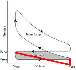
Well, keep in mind that the right-most part of your line would never go below P(man).
The blue line represents would would happen, for a throttle that was just cracked (for instance, if part-throttle engine operation were attempted with too large a throttle body):

See how the blue line quickly drops from P(man) and drops almost to the bottom of the graph. This is because the piston is sucking in more air than the throttle can provide. As the piston slows down and goes to bottom dead center, the cracked throttle is able to provide enough air to lessen the vacuum.
This is how ITBs gained a reputation for having driveability problems, particularly with a lack of torque. At part-throttle operations just above idle, they actually do more pump work just to suck in air than with a normal single throttle/intake manifold setup. Worse yet, it's a non-linear function that describes how the pump work lessens as the throttle is progressively opened up. It becomes an engineering challenge to control throttle response at this point.