I decided to take a few days to think about this, sleep on it, research a little more and decide what I want to do. I am definitely behind as I will have to learn on the fly how to set everything up as my Arduino knowledge is nothing and my car knowledge is minimal at best. That just means I will continue to have lots of questions throughout this process.

Quote:
Originally Posted by Occasionally6

That would be like using two measuring tapes; there's no need. A gyroscope (unless that's what you meant) would add additional data. That could work too/instead.
|
But shouldn't we measure twice and cut once?

JK, that makes sense. From what I have read, gyros tend to be highly accurate, but drift and accelerometers tend to be less accurate, but don't drift, is that right? So for the best accuracy, I should have both and in the Sketch write in the equation to use both. Would something like this work? It has a +/-2g accel.
Accelerometer/Gyro I can't seem to find one built into one module with a +/-1.5g accel. I'm not sure what to look for in a gyro. I can do two separate shields, but 1 would be simpler and cleaner.
Quote:
Originally Posted by Occasionally6
When doing things like this I will make a patch harness. Find a wreck (junkyard) and cut off the terminal connector of the equivalent ECU or VSS harness with ~6-8" of the wire still attached.
Unpin the VSS ECU wire or use the VSS connector intact and replace it with the salvaged wire + pin socket or connector. (Be careful not to damage the terminal if unpinning - practice on the wreck).
Solder a pin (same diameter as that which is used on the ECU) or terminals (for connection at the VSS) to the 6-8" of wire (cut it shorter to suit) and attach the vehicle terminal or connector to that. Use heat shrink to protect the terminals against a short circuit.
You can then splice into the new wire without damaging the car wires and return the wiring to stock when you remove the accessory.
|
I get what you're saying about the patch harness and I like that idea so I don't need to make any permanent cuts. My only problem is I'm a little confused about the execution of it. How do I attach the patch harness to the OEM harness? I'm not getting how to do that without cutting in or doing anything permanent to the OEM harness.
Quote:
Originally Posted by Occasionally6
You will need to modify the signal on the splice before feeding it into the Arduino. It needs to be between 3V and 5V, not exceed the current limit for the Arduino pin and not pull the signal down so far it affects the VSS input to the ECU.
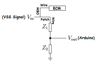
The way to do it is to put a voltage divider in the splice wire, which is connected to earth. The signal to the Arduino is taken from between the two resistors. The ratio of each resistor to the total resistance is such that the voltage drops give 5V at the point between the two resistors.
The total resistance should be as high as you can use and still get the Arduino to detect the speed input. Total resistance too low will pull the VSS signal to the ECU down. I would start with 10M Ohm and 8.2M Ohm 0.5W resistors (the closest that you can buy to the 8 Ohm a simple V=IR calculation would suggest) and go progressively lower if the Arduino doesn't work with that.
Don't go below 600 Ohm between the VSS signal wire and the Arduino (that will limit the current into the Arduino to < 10mA). Also check that the VSS signal to the ECU is still ~11V. Also check that the VSS signal voltage is actually 11V with the engine running (i.e. with the alternator supplying ~14V). If it goes higher with the engine running you will need a different ratio in the voltage divider to get the 5V.
I would build that circuit on a piece of veroboard (or similar) and put it in a potting box.
|
Just wanted to make sure I understand how the voltage divider works. I did a little mock up, using the Wikipedia pic, is this right?
So the
difference between the two resistors is what gives the Vout, so the size of the resistor doesn't matter as long as there is a difference (the size matters for current, but not for voltage)?
Can you explain how the V=IR works out to 8M ohms please? So if 5volts and 8.2Mohm, an online calculator says that would mean amps is 6.09e-7. Is that right? I need to have it less than 40milliamps (I think), but that is way less according to the calculator.
Is this what you are talking about?
8.2M ohm resistor What does the % mean?
Quote:
Originally Posted by Occasionally6
Each output - x, y and z - from the analog (i.e. not I2C) 3-axis board needs a separate analog pin. You might want one more of those reserved if you anticipate multiple switch inputs. You're going to run out of pins if you want to use gyro and linear accel. with analog inputs, and want to use a voltage divider on an analog pin for multiple switch inputs as well. You can still use the other pins as digital inputs for switches. You do have 6 pins already used by the LCD module.
|
It looks like I will have to get the MEGA board. The UNO only has 6 analog inputs, which sounds like won't be enough. 3 for the accel., 3 for the gyro, 1 for the VSS, and any others I might need. If I get the MEGA, I will know I have enough pins to do what I want and have extra for any other projects I want to do. I put the display I would like to use in the
parts list.
Common Cathode LED There is also a common anode display (in the parts list), but I'm not sure what I need (if it will work at all). It says it uses 10 pins, but I wasn't sure if I can use that for an Arduino setup. If it will work with the Arduino, I assume it uses digital pins.
Quote:
Originally Posted by Occasionally6
You might be able to use a gyro to "dead reckon" the angle i.e. integrate angular acceleration (as for the linear accelerations) to get the total angle moved from a reference point. The integration in Arduino can't be a perfect sum of the accelerations so you would need to reset periodically back to a known starting angle avoid a creeping error.
|
I found a forum where somebody has figured out how to setup a gyro and accel. and eliminate the creep.
Creep elimination Would this help so I don't have to reset to the starting angle?
Quote:
Originally Posted by Occasionally6
You might use a situation where there is no change in any of the accelerations for a period of time, like 5 seconds, and/or the vector sum is equal to 1g to indicate the car is stopped. Then use the fact that the linear acceleration will only be that due to gravity when at rest. If you're on a slope in that situation you would use trig. to determine the angles.
|
Would this be done to eliminate creep? Would this be necessary with the Kalman filter. Would there be a way to set it up so that after so at a set time (using the time code:
time), say 5:00AM, the arduino will reset itself? I don't know if there is a way for the Arduino to automatically come on and then shutoff after re-calibration.The idea would be that when I am at home (parked in the same spot as always), it will reset and the angle of the car would then be implied. Again though, would this be necessary with the filter?