Quote:
Originally Posted by Occasionally6

That one uses I2C for the output.
|
I can't seem to find one that is an analog output. The MPU-6050 says "I2C Digital-output of 6 or 9-axis MotionFusion data in rotation matrix, quaternion, Euler Angle, or raw data format". Is the 'raw data format' not analog?
What about this one:
L3G4200D It says it has the option to output in SPI. I've tried looking that up, but can't find if it is analog or digital. Would SPI work for me?
Quote:
Originally Posted by Occasionally6
The easiest way to explain what happens to the VSS signal if the resistance in the extra circuit is too low, is to take it to the extreme and place no resistor (R1 + R2 = 0) in the spliced in wire that is connected to earth. The VSS signal is then shorted to ground and never goes high i.e. there's no longer a VSS signal.
|
Thanks, that makes sense now.
Quote:
Originally Posted by Occasionally6
1/2W will be OK.
|
What does the wattage rating mean? Is it the max watts the resistor can handle? So if I happened to buy 1W, that would work (just be a little overkill)?
Quote:
Originally Posted by Occasionally6
As it's a square wave it only has two states: high (= 5V or even ~11V) and low (= 0V). That's a digital signal.
|
OK. As a side note, how does it determine the speed, the size of the wavelength?
Quote:
Originally Posted by Occasionally6
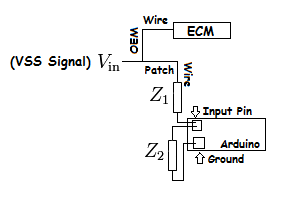
If I understand you, not quite. One end of R1 is connected to the VSS signal, the other end of R1 to the Arduino input pin. One end of R2 is also connected to the 5V Arduino input pin, the other end of R2 is connected to ground, whether on the car or on the Arduino.
Because the VSS and Arduino will nominally share a common ground potential it shouldn't matter whether you connect the ground end of R2 to a ground on the car or to one on the Arduino.
Because there will almost certainly be small differences in the ground potentials, and you want the potential of 5V to be across the Arduino input and ground pins, it's probably better to make the ground (and check the potential across it and the nominally 5V signal) at the Arduino. Be careful because if you exceed 5V you will be implementing one of the 10 ways to destroy an Arduino.
|
So something like this then?:
I was looking for a DMM on Amazon and of course, about a million different ones came up. I want an inexpensive one, but is there something I should look for?
Any idea on what size veroboard I will need (approximately)? Would a 2x3" board be big enough?
Veroboard