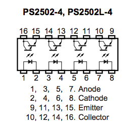
Yesterday I picked up a couple of PS2502-4 opto-isolators (4-channel):

I started to play around with it at home: a 0-5K pot (as a variable resistor) putting 5V into pins 1 & 2, and an LED load on 15 & 16, powered by a 20V AC-DC converter through a 1K resistor.
What I found is that the output is much more controllable by the input than a plain transistor. A transistor will trigger full blast with a 10K resistor on the gate. Even a 100K resistor. This chip needs more current, and I found that output basically peaks with a 220 ohm resistor into pins 1 & 2, drawing 13.7mA. And that's good, because the Arduino will have plenty of juice to power it.
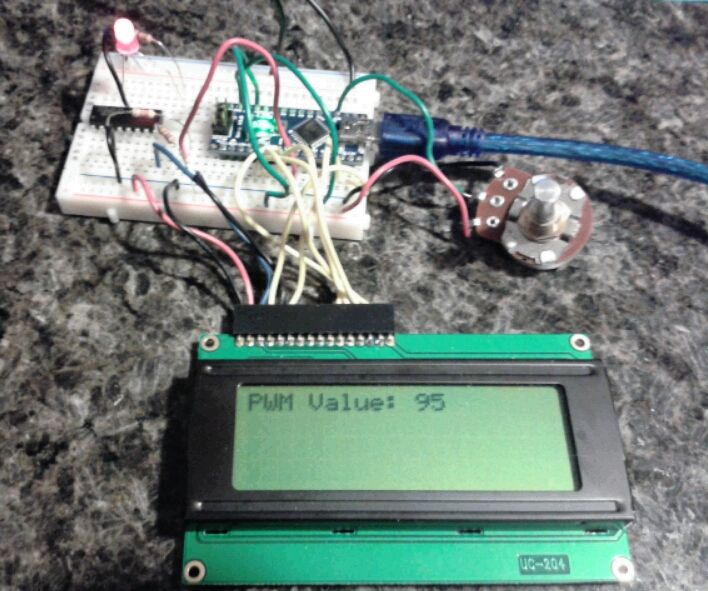
I also tested to see how it responds with PWM and it works just fine. I will use my little PWM program to find PWM calibration values for the fuel and temperature gauges.

Quote:
#include <LiquidCrystal.h>
int potPin = 0; // Potentiometer pin
int PWMout = 6; // Output to optoisolator
LiquidCrystal lcd(12, 11, 5, 4, 3, 2);
void setup() {
pinMode(potPin, INPUT);
pinMode(PWMout, OUTPUT);
lcd.begin(20, 4);
}
void loop() {
int value = map(analogRead(potPin), 0, 1023, 0, 255);
analogWrite(PWMout, value);
lcd.setCursor(11, 0);
lcd.print(" ");
lcd.setCursor(0, 0);
lcd.print("PWM Value: ");
lcd.print(value);
delay(100);
}
|