 03-22-2014, 09:18 PM
|
#11 (permalink)
|
|
EcoModding Lurker
Join Date: Apr 2011
Location: Reseda,Ca
Posts: 22
Thanks: 0
Thanked 7 Times in 4 Posts
|
Great project! I was thinking about how to use an arduino for a charge controller for a battery cycler I'm building and here it is  . Keep up the good work.
Joe
|
|
|

|
 Today Today
|
|
|
|
 Other popular topics in this forum...
|
|
|
|
 03-25-2014, 01:23 AM
|
#12 (permalink)
|
|
Master EcoModder
Join Date: Jul 2008
Location: Langley, BC
Posts: 1,228
Fusion - '16 Ford Fusion Hybrid SE
Thanks: 190
Thanked 275 Times in 168 Posts
|
I was driving home from work the other day when I glanced at my fuel and temperature gauges, which currently do nothing, and suddenly thought, "man...I could totally put those to use now!!"
So today I found the wires that go to the ex-coolant temp and fuel level senders. When I ground the former, it draws 220mA and the coolant temp gauge pins to the max. When I ground the latter, it draws 117mA and the fuel gauge slowly moves to full. This will be incredibly simple to do....simply control current with an NPN transistor on each, feeding each a calibrated PWM.
Actually...I will use opto-isolators to keep the 12V accessory side isolated from the 72V pack side that the Arduino will be in bed with. However, I do not know what their characteristics are compared to regular old transistors. Something tells me they take a lot more current to trigger/switch than transistors which take hardly anything. I may have to up the Arduino's juice with a transistor to trigger an opto-isolator. I must acquire one ASAP and do some playing.
|
|
|

|
|
The Following User Says Thank You to mechman600 For This Useful Post:
|
|
 03-25-2014, 07:35 AM
|
#13 (permalink)
|
|
Dreamer
Join Date: Nov 2013
Location: Australia
Posts: 350
Thanks: 95
Thanked 214 Times in 151 Posts
|
Quote:
Originally Posted by mechman600

...
Actually...I will use opto-isolators to keep the 12V accessory side isolated from the 72V pack side that the Arduino will be in bed with. However, I do not know what their characteristics are compared to regular old transistors. Something tells me they take a lot more current to trigger/switch than transistors which take hardly anything. I may have to up the Arduino's juice with a transistor to trigger an opto-isolator. I must acquire one ASAP and do some playing.
|
I believe the driven side of the opto is just a led.
So between 4 and 20mA normally.
Someone correct me if this is wrong. |
|
|

|
 03-25-2014, 11:27 AM
|
#14 (permalink)
|
|
Administrator
Join Date: Dec 2007
Location: Germantown, WI
Posts: 11,203
Thanks: 2,501
Thanked 2,589 Times in 1,555 Posts
|
You're correct.
|
|
|

|
 03-25-2014, 02:14 PM
|
#15 (permalink)
|
|
Master EcoModder
Join Date: Jul 2008
Location: Langley, BC
Posts: 1,228
Fusion - '16 Ford Fusion Hybrid SE
Thanks: 190
Thanked 275 Times in 168 Posts
|
Quote:
Originally Posted by Astro

I believe the driven side of the opto is just a led.
So between 4 and 20mA normally.
Someone correct me if this is wrong.
|
Yup, that's right. It would be nice if it only took 20mA to fully trigger, as the Arduino can do 40mA per pin max output. If it takes more than 40mA I will have to amplify the signal with a transistor. |
|
|

|
 03-26-2014, 10:58 AM
|
#16 (permalink)
|
|
Master EcoModder
Join Date: Jul 2008
Location: Langley, BC
Posts: 1,228
Fusion - '16 Ford Fusion Hybrid SE
Thanks: 190
Thanked 275 Times in 168 Posts
|
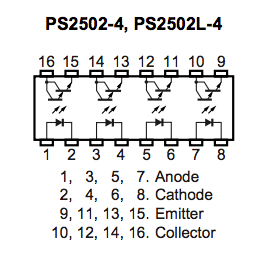
Yesterday I picked up a couple of PS2502-4 opto-isolators (4-channel):

I started to play around with it at home: a 0-5K pot (as a variable resistor) putting 5V into pins 1 & 2, and an LED load on 15 & 16, powered by a 20V AC-DC converter through a 1K resistor.
What I found is that the output is much more controllable by the input than a plain transistor. A transistor will trigger full blast with a 10K resistor on the gate. Even a 100K resistor. This chip needs more current, and I found that output basically peaks with a 220 ohm resistor into pins 1 & 2, drawing 13.7mA. And that's good, because the Arduino will have plenty of juice to power it.
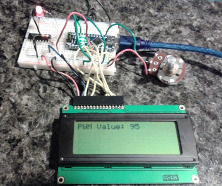
I also tested to see how it responds with PWM and it works just fine. I will use my little PWM program to find PWM calibration values for the fuel and temperature gauges.

Quote:
#include <LiquidCrystal.h>
int potPin = 0; // Potentiometer pin
int PWMout = 6; // Output to optoisolator
LiquidCrystal lcd(12, 11, 5, 4, 3, 2);
void setup() {
pinMode(potPin, INPUT);
pinMode(PWMout, OUTPUT);
lcd.begin(20, 4);
}
void loop() {
int value = map(analogRead(potPin), 0, 1023, 0, 255);
analogWrite(PWMout, value);
lcd.setCursor(11, 0);
lcd.print(" ");
lcd.setCursor(0, 0);
lcd.print("PWM Value: ");
lcd.print(value);
delay(100);
}
|
|
|
|

|
 03-26-2014, 11:30 AM
|
#17 (permalink)
|
|
Master EcoModder
Join Date: Oct 2012
Location: USA
Posts: 1,408
Thanks: 102
Thanked 252 Times in 204 Posts
|
150ma collector emitter max on those optos, sounds like your "fuel" meter will work as-is, but the temp meter current is a bit high, but sounds like it needs some more resistance anyway (probably the original sensor wasn't 0 ohms at max temp, 12v+pot to determine FSD ohms). You are making it look easy  |
|
|

|
 03-28-2014, 03:28 AM
|
#18 (permalink)
|
|
Master EcoModder
Join Date: Jul 2008
Location: Langley, BC
Posts: 1,228
Fusion - '16 Ford Fusion Hybrid SE
Thanks: 190
Thanked 275 Times in 168 Posts
|
Today I went about testing the fuel and temp gauges with my simple PWM circuit and program. My LCD screen displayed "PWM Value", which is an 8-bit value (0-255).
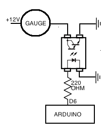
Here is the circuit:

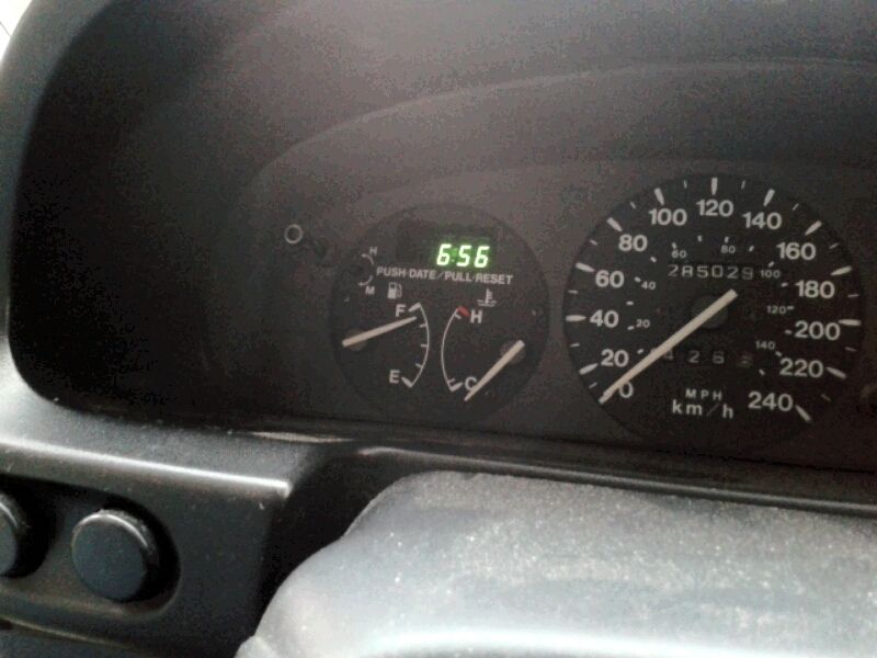
The coolant temp circuit worked great. The PWM range from the needle just barely off the bottom to the "H" line at the top is 60 to 185. This calibration will look something like this:
Quote:
temp_PWM_out = map(temp_F, 30, 225, 60, 185);
analogWrite(tGauge_pin, temp_PWM_out);
|
The 30 and 225 represent the min and max values (in Fahrenheit) that I want the gauge to read and the 60 and 185 represent the min and max PWM value that the temp will map to.
The fuel gauge did not work as well. The fuel gauge needs a very low resistance to show "full". The PS2502 opto-isolator's 1V collector emitter saturation voltage (woah, did I just write that??) keeps the gauge from getting past 7/8 full with the PWM at 255. I tried increasing the current into the diode side of the opto-isolator by using a smaller resistor but this didn't change anything. Empty happens at PWM 115. Oh well, I tried. I guess 7/8th of a tank is all I will get.

This will look like this:
Quote:
fuel_PWM_out = map(fuel_level, 0, 100, 115, 255);
analogWrite(fGauge_pin, fuel_PWM_out);
|
|
|
|

|
 03-28-2014, 04:13 AM
|
#19 (permalink)
|
|
Master EcoModder
Join Date: Oct 2012
Location: USA
Posts: 1,408
Thanks: 102
Thanked 252 Times in 204 Posts
|
7/8ths is plenty good. But if it is still bugging you, driving a mosfet with the opto might get you the low resistance it needs for fsd.
0.107ohms @ 150ma = 0.016v drop across the mosfet ($0.29).
RFD3055LE Fairchild Semiconductor | Mouser |
|
|

|
 03-28-2014, 10:58 AM
|
#20 (permalink)
|
|
Master EcoModder
Join Date: Jul 2008
Location: Langley, BC
Posts: 1,228
Fusion - '16 Ford Fusion Hybrid SE
Thanks: 190
Thanked 275 Times in 168 Posts
|
Quote:
Originally Posted by P-hack

7/8ths is plenty good. But if it is still bugging you, driving a mosfet with the opto might get you the low resistance it needs for fsd.
|
I tried this with a 2N7000, but I could not make it work for the life of me. It either stayed switched on (no matter what PMW value) or if I switched resistors to different spots (like a 5K from the 2N7000's gate to ground), my test LED switched on when PWM was 1 but the current did not increase as I turned it up. 
|
|
|

|
|