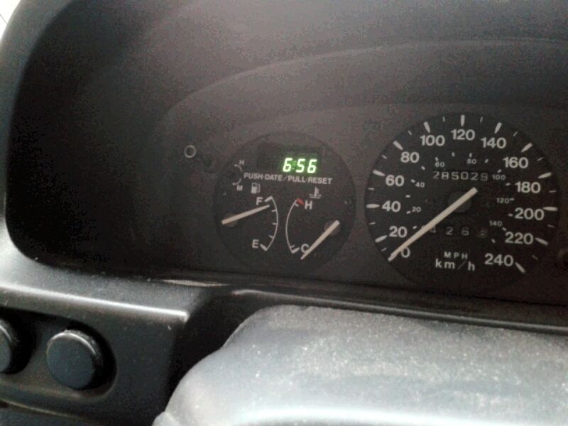
Today I went about testing the fuel and temp gauges with my simple PWM circuit and program. My LCD screen displayed "PWM Value", which is an 8-bit value (0-255).
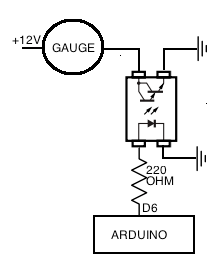
Here is the circuit:
The coolant temp circuit worked great. The PWM range from the needle just barely off the bottom to the "H" line at the top is 60 to 185. This calibration will look something like this:
Quote:
temp_PWM_out = map(temp_F, 30, 225, 60, 185);
analogWrite(tGauge_pin, temp_PWM_out);
|
The 30 and 225 represent the min and max values (in Fahrenheit) that I want the gauge to read and the 60 and 185 represent the min and max PWM value that the temp will map to.
The fuel gauge did not work as well. The fuel gauge needs a very low resistance to show "full". The PS2502 opto-isolator's 1V collector emitter saturation voltage (woah, did I just write that??) keeps the gauge from getting past 7/8 full with the PWM at 255. I tried increasing the current into the diode side of the opto-isolator by using a smaller resistor but this didn't change anything. Empty happens at PWM 115. Oh well, I tried. I guess 7/8th of a tank is all I will get.
This will look like this:
Quote:
fuel_PWM_out = map(fuel_level, 0, 100, 115, 255);
analogWrite(fGauge_pin, fuel_PWM_out);
|