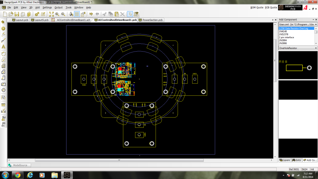
That's a very interesting idea. I don't think I can get the mechanics to work out though. There wouldn't be enough room. See those colorful electronic blocks? (there are 2 separate "blocks" in this picture). There would have to be 6 of those (but 4 could be made to work, but that has other issues). Then you would need the control circuitry somewhere. Also, I'm not sure how it would bolt together. If we bolt the capacitor to the rings first, how do we get access to the 3 C1's? If we bolt to the IGBTs first, then the inner ring of tabs on the cap is inaccessible (it's right against the IGBT case. About 0.1" of clearance). You could have 2 separate B- rings and 2 separate B+ rings. But then you'd have to add something like a conductive epoxy, since you would need good contact to keep the loop area small.
The base plate would be 14.5" x 12.5" or so. The way I had planned to do was 15" x 12". Your approach would reduce the height of the controller by around 0.85". So, it would be a smaller volume, I think... Yes, it would be 75% of the original volume.