Go Back   EcoModder Forum > EcoModding > Fossil Fuel Free
Register Now
 Register Now
 

Reply  Post New Thread
 
Submit Tools LinkBack Thread Tools
Old 08-06-2014, 12:44 PM   #871 (permalink)
PaulH
 
MPaulHolmes's Avatar
 
Join Date: Feb 2008
Location: Maricopa, AZ (sort of. Actually outside of town)
Posts: 3,832

Michael's Electric Beetle - '71 Volkswagen Superbeetle 500000
Thanks: 1,368
Thanked 1,202 Times in 765 Posts
I think Fran used a 64 ticks/rev encoder that worked fine for FOC.

__________________
kits and boards
  Reply With Quote
The Following User Says Thank You to MPaulHolmes For This Useful Post:
Astro (08-06-2014)
Alt Today
Popular topics

Other popular topics in this forum...

   
Old 08-10-2014, 11:28 PM   #872 (permalink)
Dreamer
 
Join Date: Nov 2013
Location: Australia
Posts: 350
Thanks: 95
Thanked 214 Times in 151 Posts
Paul,
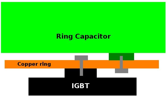
Ever since i saw the copper sheet connecting the IGBT's to the Ring cap i have thought why not use something more solid.
Apologies for the terrible sketch.

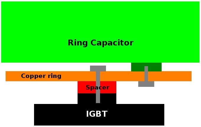
I thought two concentric copper rings could be used instead. The material could be thick enough to provide some mechanical strength to the IGBT to ring cap connection. Maybe 4mm thickness or so?
Also with the driver PCB under the ring cap the whole controller enclosure could be about one third smaller.
In the sketch the IGBT's (blue) mount to the base heatsink, then the two rings of copper (orange) bolt to them, then the ring cap (green) mounts on top of the rings.
The thickness of the ring material could be increased to provide more mechanical strength and the inside/outside diameters of the rings changed to provide increased current flow area.
Hopefully the polarities work out ok, i was just basing it off of some of the photos of the controller not the schematic.
The positioning of the IGBT's could be moved a bit to allow for a rectangular PCB.
Or the IGBT's at East and West could be moved to SE and SW making the output connections easier as long as the current flows still work out ok. I just set them at east west and south so that they remained square to each other.

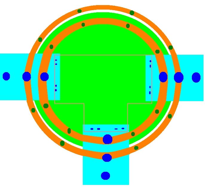
Using the rings would also give much larger clearances between conductors. The rings could be powder coated if required (not where the bolts go though) to increase the electrical insulation.
The PCB has all the space to the north that it can be expanded into if required to make getting at the low voltage connections easier.

What do you think?
  Reply With Quote
The Following 2 Users Say Thank You to Astro For This Useful Post:
flores (08-11-2014), MPaulHolmes (08-11-2014)
Old 08-11-2014, 08:39 AM   #873 (permalink)
Dreamer
 
Join Date: Nov 2013
Location: Australia
Posts: 350
Thanks: 95
Thanked 214 Times in 151 Posts
Another thought.

If this configuration was possible then it would give the battery connections something much stronger to bolt to. There also wouldn't be any issue with the lug touching the incorrect sheet of copper. The battery lugs could have their own mounting points and not have to share with the ring cap. So the ring cap could then be removed for maintenance etc.without disturbing the battery or motor connections.

I was thinking of using some flat copper bar that i have (19x3.2mm) and getting a fabricator to put it through the rollers and make some neat rings from it. Then weld the joint.
60mm2 of copper should carry a bit of current. If it isn't enough then i could just stack multiple rings on top of each other to get to the required square mm.
  Reply With Quote
Old 08-11-2014, 10:35 AM   #874 (permalink)
PaulH
 
MPaulHolmes's Avatar
 
Join Date: Feb 2008
Location: Maricopa, AZ (sort of. Actually outside of town)
Posts: 3,832

Michael's Electric Beetle - '71 Volkswagen Superbeetle 500000
Thanks: 1,368
Thanked 1,202 Times in 765 Posts


That's a very interesting idea. I don't think I can get the mechanics to work out though. There wouldn't be enough room. See those colorful electronic blocks? (there are 2 separate "blocks" in this picture). There would have to be 6 of those (but 4 could be made to work, but that has other issues). Then you would need the control circuitry somewhere. Also, I'm not sure how it would bolt together. If we bolt the capacitor to the rings first, how do we get access to the 3 C1's? If we bolt to the IGBTs first, then the inner ring of tabs on the cap is inaccessible (it's right against the IGBT case. About 0.1" of clearance). You could have 2 separate B- rings and 2 separate B+ rings. But then you'd have to add something like a conductive epoxy, since you would need good contact to keep the loop area small.

The base plate would be 14.5" x 12.5" or so. The way I had planned to do was 15" x 12". Your approach would reduce the height of the controller by around 0.85". So, it would be a smaller volume, I think... Yes, it would be 75% of the original volume.
__________________
kits and boards

Last edited by MPaulHolmes; 08-11-2014 at 10:46 AM..
  Reply With Quote
Old 08-11-2014, 11:51 AM   #875 (permalink)
Dreamer
 
Join Date: Nov 2013
Location: Australia
Posts: 350
Thanks: 95
Thanked 214 Times in 151 Posts
Man you make my drawing look... nah can't think of a word to describe how bad you make my drawings look.

I am trying to picture where the close spacing is between the capacitor tab mounting and the IGBT. The horizontal spacing on your drawing looks good so it must be the vertical spacing.
I thought as the IGBT bolt holes were raised compared to the rest of the IGBT that there would have been room for the capacitor bolt heads even if they were over the IGBT. I was expecting to have to put the bolts for the ring capacitor through the copper ring before bolting the ring down to the IGBTs but once they were in it would only be the bolt head that was below the copper ring near the IGBT. And for the IGBT it would only be their bolt heads that would be on top of the copper ring near the capacitor.

Rather than a second set of rings maybe just some simple copper spacers to give more vertical clearance?

Stand by for some more nasty drawings.


Without spacers.


With spacers.


I was thinking that the space north of centre could be used for the control circuitry. As there are IGBTs to the east, south and west but nothing north. (maybe i should do another dodgy diagram )
If the controller circuitry could be positioned there then there would be very little space required beyond the north of the edge of the ring capacitor. That would shorten the enclosure quite a bit.

Ahhhh.... Just had another look at the photo's and the bolts for the inner tabs of the ring capacitor have a screw type head (phillips head) which would be inaccessible once the rings were bolted to the IGBTs. I had thought they were all hex headed bolts so only access for a small spanner was required.
Couldn't those screw head bolts be swapped out for some hex headed bolts?

Or i could be misunderstanding the whole issue. (much more likely)

Last edited by Astro; 08-11-2014 at 12:08 PM.. Reason: Spelling, again.
  Reply With Quote
The Following User Says Thank You to Astro For This Useful Post:
MPaulHolmes (08-11-2014)
Old 08-11-2014, 03:35 PM   #876 (permalink)
PaulH
 
MPaulHolmes's Avatar
 
Join Date: Feb 2008
Location: Maricopa, AZ (sort of. Actually outside of town)
Posts: 3,832

Michael's Electric Beetle - '71 Volkswagen Superbeetle 500000
Thanks: 1,368
Thanked 1,202 Times in 765 Posts
Uh oh, now we're significantly increasing the loop area. The only reason for doing a laminated bus (like before) is to have small loop area. Increasing the loop area will increase voltage spikes at turn-off of the IGBT. The path from CAPACITOR PLUS to IGBT C1 to IGBT C2/E1 to IGBT E2 to CAPACITOR MINUS to CAPACITOR PLUS must have an AREA that's as small as possible.

dv/dt = strayInductance*di/dt

The di/dt will be very big. Like 400amp in a microsecond. So,

di/dt = 400,000,000. dv/dt is the turnoff spike and must be kept under, say, 100v (300v bus + 100v is 400v). We don't want to get near the 600v limit of the IGBT. So, stray inductance must be below:

100/400,000,000 = strayInductance

250nanoHenries = strayInductance

The laminated bus with that capacitor can have a stray inductance in the neighborhood of 5 nanoHenries.

This has the formula for inductance of a rectangular loop. I'm not sure what the area would be, but you could try to plug in the values, and see how many nanohenries you get out:

http://www.technick.net/public/code/...ance_rectangle
__________________
kits and boards

Last edited by MPaulHolmes; 08-11-2014 at 04:08 PM..
  Reply With Quote
Old 08-11-2014, 08:38 PM   #877 (permalink)
Dreamer
 
Join Date: Nov 2013
Location: Australia
Posts: 350
Thanks: 95
Thanked 214 Times in 151 Posts
So without using the spacer and just swapping the inner capacitor tab bolt to a hex head would there be enough clearance to get a a small spanner in there to tighten the bolt?

Those inductance calculations are tricky. With the varying material thickness (ring, IGBT internals, capacitor tab, capacitor internals) the figures vary quite a bit. But i did notice that the radius of the conductor had a huge effect on the result. Just a small increase in the radius caused a huge reduction in the overall inductance figure. So the large cross-sectional area of the copper ring should help reduce the inductance.
I believe the calculator assumes a round conductor which means it is difficult to enter high radius numbers without it complaining of invalid parameters. The copper rings will have a large cross-sectional area but low height. So the rectangle could have a height so low that if the conductor was round the opposite sides of the rectangle would touch but with a flattened conductor the low rectangle height is achievable.
I guesstimated many of the parameters.
But a 60mm by 25mm rectangle will be around the 10nH inductance if you can get the conductor radius up to around 12mm.
Because the IGBT connections would be slap bang in the middle between two capacitor tabs would the cross-sectional area of the two connections (one to each capacitor tabs) combine to lower the inductance? Or would the inductance combine to double the inductance?
I do know for sure that it is way too early in the morning for maths. I was so engrossed in creating my dodgy diagrams last night that i only left 4 hours for sleep before the alarm insisted i go to work.
I better put heaps of comments on the software i write today because it is sure to slightly crazy.
These sort of problems sound like just the thing that students would love their teacher to challenge them with.
  Reply With Quote
The Following User Says Thank You to Astro For This Useful Post:
MPaulHolmes (08-11-2014)
Old 08-11-2014, 10:54 PM   #878 (permalink)
PaulH
 
MPaulHolmes's Avatar
 
Join Date: Feb 2008
Location: Maricopa, AZ (sort of. Actually outside of town)
Posts: 3,832

Michael's Electric Beetle - '71 Volkswagen Superbeetle 500000
Thanks: 1,368
Thanked 1,202 Times in 765 Posts
1.14" - 0.83" is the clearance. that's more than I thought. 0.31 inch They make wrenches that skinny I bet. But how on earth do you fit the electronics inside there??? Were you suggesting to open the ring on the north side?
__________________
kits and boards
  Reply With Quote
Old 08-12-2014, 02:39 AM   #879 (permalink)
Dreamer
 
Join Date: Nov 2013
Location: Australia
Posts: 350
Thanks: 95
Thanked 214 Times in 151 Posts
I hadn't pictured it clearly in my head but i was thinking that as there was no IGBT to the north, that area could be used. Thinking that the clearance between the heat sink and the bottom side of the copper ring would be enough to allow the control circuits to utilise the space to the north right to the edge of the heat sink if required.
However i can see there would probably be issues with the control circuits getting too close to the copper rings even if the PCB stepped down to a lower level closer to the heat sink.
What about if there were two separate boards one above the other, the lower board carrying the control circuits and the upper board just the drivers? The lower board almost touching the heat sink and the upper board at the correct level to solder directly to the driver pins on the IGBTs. That way the circuits would all remain within the confines of the inner copper ring.

Actually i should probably stop making suggestions. You have put an enormous amount of effort into the existing design and what i am suggesting is looking more and more like a total redesign.

Maybe best to go with what already works. Sorry to waste your time answering all these questions. I didn't expect it to snowball so much but i suppose that's how it goes sometimes. One change requires two more changes which require two more changes each and hey presto the whole design has changed. Maybe it should just be something to mull over until hardware version 2 is being designed.

I get people asking me things like this all the time in software development land. "We just want one small change, won't take you long" and it leads to a total rewrite and months of work.
  Reply With Quote
The Following User Says Thank You to Astro For This Useful Post:
MPaulHolmes (08-12-2014)
Old 08-12-2014, 01:55 PM   #880 (permalink)
PaulH
 
MPaulHolmes's Avatar
 
Join Date: Feb 2008
Location: Maricopa, AZ (sort of. Actually outside of town)
Posts: 3,832

Michael's Electric Beetle - '71 Volkswagen Superbeetle 500000
Thanks: 1,368
Thanked 1,202 Times in 765 Posts
haha, I know!

Oh I just submitted the AC control/driver board a minute ago. I paid extra for the setup fee so the board will be white. I thought it would look cool. silver and white, with black silkscreen. I checked and recheck it. Errors got more and more minor, and asymptotically decreased to what appeared to be zero after many checks. It's as through-hole as I could make it. It's pretty simple in principle. I put the probability of it spinning a motor at 99.99999%. I put the probability of it being able to move a car at 99.999%.

__________________
kits and boards
  Reply With Quote
The Following 2 Users Say Thank You to MPaulHolmes For This Useful Post:
Astro (08-13-2014), flores (08-13-2014)
Reply  Post New Thread


Similar Threads
Thread Thread Starter Forum Replies Last Post
Paul & Sabrina's cheap DIY 144v motor controller MPaulHolmes Open ReVolt: open source DC motor controller 7381 08-02-2023 10:55 PM
Paul & Sabrina's Cheap EV Conversion MPaulHolmes Fossil Fuel Free 542 11-12-2016 09:09 PM
Contest! Name Paul & Sabrina's controller MetroMPG Forum News & Feedback 120 10-22-2011 01:59 PM


Powered by vBulletin® Version 3.8.11
Copyright ©2000 - 2024, vBulletin Solutions Inc.
Content Relevant URLs by vBSEO 3.5.2
All content copyright EcoModder.com