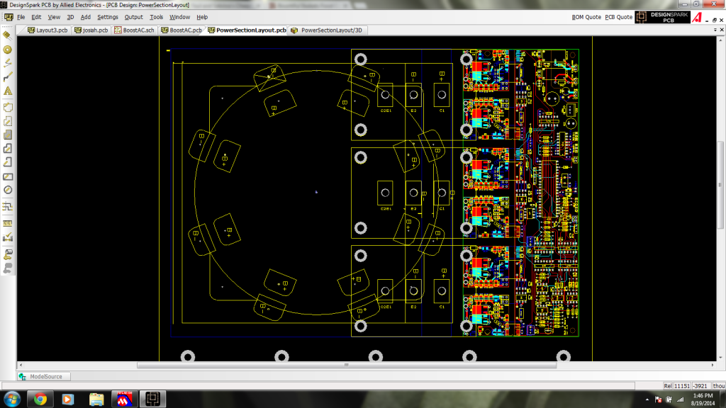
Actually, I think I'll try this. You can fuse the output cap of the boost converter and input cap of the AC controller into 1. So, the layout works out in an incredibly clean way. Instead of 3 IGBTs plugged into the control/driver board (like on the regular old AC controller), and also bolted to the ring capacitor, you have 4 plugged into the (not yet existing) control/driver board. And bolt all 4 igbts in exactly the same way to the ring capacitor. Then, instead of 3 cables heading out (for U, V, W), you have 4 cables. 3 go to the AC motor, and one goes to an inductor. The other side of the inductor goes to the battery pack +. Done! I was thinking of a separate little box for the inductor. The 1200v 600amp IGBTs have the same footprint and dimensions as the 600v 600amp IGBTs, so you could boost 300v at 200amp to 600v at 100amp with a stock $340 inductor.
So, instead of the following picture, you would have 4 IGBTs. You would have to switch out the dsPIC30F4011 for the dsPIC30F6015, which has PWM1L, PWM1H, ..., PWM4L, PWM4H. Use pwm4l and pwm4h for controlling the 4th IGBT's pwm:
