Next, is the right side of the assembly, which I call the "resolver" side.
Here is the resolver itself, and the inside of the resolver side.
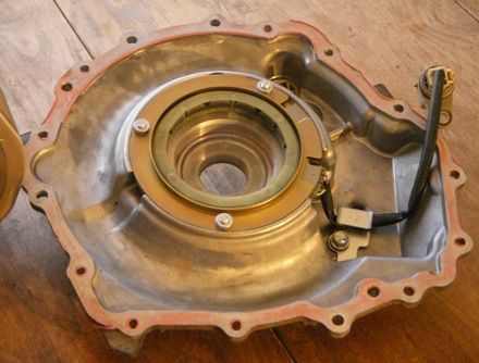
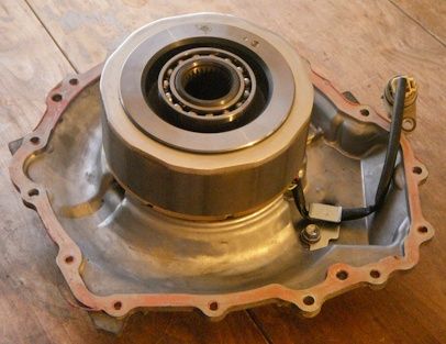
You may have noticed a space for a ball bearing in the previous photos of the stator. Note there is also space for a ball bearing centered in the resolver. The motor's rotor actually runs on ball bearings nestled within the rotor itself. A spline on the rotor transfers torque to the first driveshaft. Here is a shot of the rotor fitting on it's bearing space on the resolver side.
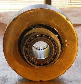
Here is a closup of the rotor, looking at the resolver side. Note the semicircular resolver rotor just behind the bearing.
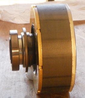
An side view of the rotor. The resolver (between the bearing and main laminations) is only a few laminations thick.
The gearbox side of the rotor. The bearing is nestled in the laminations; also note the output spline.
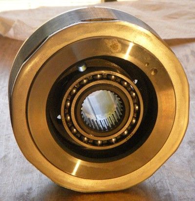
The rotor OD is 5.825" (148mm) Also note how you can only see laminations. The magnets for this rotor are buried in a "v" form. Details about the reasons for this are in the papers I posted earlier.