 08-31-2014, 03:43 AM
|
#11 (permalink)
|
|
Permanent Apprentice
Join Date: Jul 2010
Location: norcal oosae
Posts: 523
Thanks: 351
Thanked 318 Times in 215 Posts
|
I previously posted that I took one of these apart. Unfortunately, I didn't photograph the process, but suffice to say it was pretty easy and didn't require any special tools.
Basically, there are three major parts to the assembly; assembled horizontally. The oil is sealed inside with some silicone sealant, no special gaskets or huge o-rings.
Before taking it apart, I'm going to show the electrical connectors. First are the position and temperature sensors. The 6-pin connector is for the resolver, the 3 pin connector is for the temperature sensor. According to Toyota, if the ECU determines the temperature is too high, it will shut down the MGR until it fall back into the proper range.
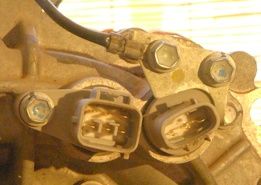
This connector is the main 3-phase power connector. Note that this part is some sort of extension to the main connector.
Locating these plugs (both data and main power) could be a real PIA, especially if it turns out Toyota is the only source.
|
|
|

|
|
The Following 2 Users Say Thank You to e*clipse For This Useful Post:
|
|
 Today Today
|
|
|
|
 Other popular topics in this forum...
|
|
|
|
|
08-31-2014, 03:59 AM
|
#12 (permalink)
|
|
Permanent Apprentice
Join Date: Jul 2010
Location: norcal oosae
Posts: 523
Thanks: 351
Thanked 318 Times in 215 Posts
|
Here are some of the guts. I'm breaking the posts up to make discussion easier. 
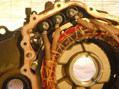
I'll start with the stator. It's part of the middle section of the assembly.
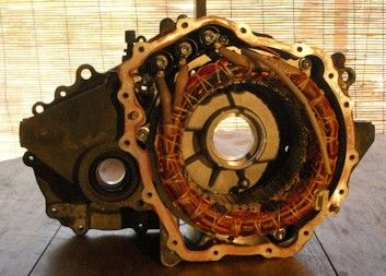
Here's a closup of the stator slots and windings. There are 48 slots. The stator OD is 235mm, and the ID is 150mm. The slot width is 45mm.
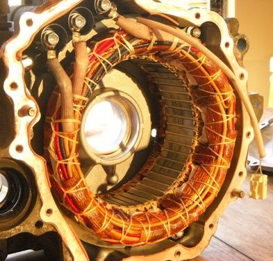
Here's a closup showing some of the winding details. The winding wire diameter (including varnish) is 0.030", close to AWG #21. There are three wire groups/phase; I think there are 12 wires/phase.
 |
|
|
|
|
The Following 2 Users Say Thank You to e*clipse For This Useful Post:
|
|
|
08-31-2014, 04:00 AM
|
#13 (permalink)
|
|
Corporate imperialist
Join Date: Jul 2011
Location: NewMexico (USA)
Posts: 11,312
Thanks: 273
Thanked 3,580 Times in 2,843 Posts
|
That pile of motors is long gone.
I am pretty sure they were opened up and the copper already harvested out.
__________________
1984 chevy suburban, custom made 6.5L diesel turbocharged with a Garrett T76 and Holset HE351VE, 22:1 compression 13psi of intercooled boost.
1989 firebird mostly stock. Aside from the 6-speed manual trans, corvette gen 5 front brakes, 1LE drive shaft, 4th Gen disc brake fbody rear end.
2011 leaf SL, white, portable 240v CHAdeMO, trailer hitch, new batt as of 2014.
|
|
|
|
|
08-31-2014, 04:23 AM
|
#14 (permalink)
|
|
Permanent Apprentice
Join Date: Jul 2010
Location: norcal oosae
Posts: 523
Thanks: 351
Thanked 318 Times in 215 Posts
|
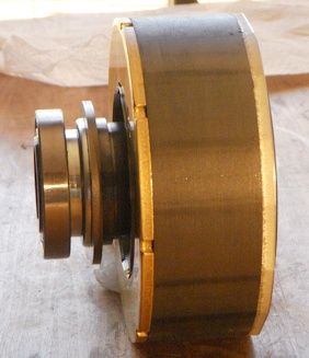
Next, is the right side of the assembly, which I call the "resolver" side.
Here is the resolver itself, and the inside of the resolver side.
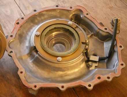
You may have noticed a space for a ball bearing in the previous photos of the stator. Note there is also space for a ball bearing centered in the resolver. The motor's rotor actually runs on ball bearings nestled within the rotor itself. A spline on the rotor transfers torque to the first driveshaft. Here is a shot of the rotor fitting on it's bearing space on the resolver side.
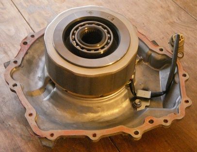
Here is a closup of the rotor, looking at the resolver side. Note the semicircular resolver rotor just behind the bearing.
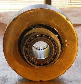
An side view of the rotor. The resolver (between the bearing and main laminations) is only a few laminations thick.
The gearbox side of the rotor. The bearing is nestled in the laminations; also note the output spline.
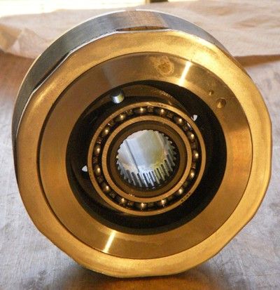
The rotor OD is 5.825" (148mm) Also note how you can only see laminations. The magnets for this rotor are buried in a "v" form. Details about the reasons for this are in the papers I posted earlier. |
|
|
|
|
08-31-2014, 05:30 AM
|
#15 (permalink)
|
|
Master EcoModder
Join Date: Aug 2012
Location: northwest of normal
Posts: 29,154
Thanks: 8,277
Thanked 9,039 Times in 7,470 Posts
|
I like the title. Bill Fisher's book How to Hot Rod Volkswagen Engines has been a classic for years.
My thought was at $400 I'd get two and use the best one. In the event I went with the $650 Lexus part. I rationalize it by saying maybe the yard knows it's worth more than others. We'll see—it should be delivered by Monday.
I've measured the vehicle and I have 11" between the frame rails. It might be tight getting the axle centerline to the original location. I may have to rotate the unit 5-10° up in front and the vertical clearance looks tight. The plan is to make a 1/8" steel plate carrier that will lie below the MGR, adapt it's mounting tabs and fit to the stock VW rubber transaxle mounts.
For benefit of those not in the AC controller thread, my hope is to use the Toyota gearset as a raw material for additional hardening and machining, and put it in an understressed installation to see if I can get by without an external oil pump.
Toyota must have training materials for their mechanics. Those mechanics must go someplace for a beer after work. Hmmmm.....
Edit: Will it be possible to drive one of Paul's controllers from 120v or 240v mains power, at a bench dynamometer?
Last edited by freebeard; 08-31-2014 at 05:38 AM..
|
|
|
|
|
08-31-2014, 10:58 AM
|
#16 (permalink)
|
|
PaulH
Join Date: Feb 2008
Location: Maricopa, AZ (sort of. Actually outside of town)
Posts: 3,832
Thanks: 1,362
Thanked 1,202 Times in 765 Posts
|
Ya, but you would need a rectifier. The capacitor filter is already there. A big fat 600v 1000uf ring cap.
|
|
|
|
|
08-31-2014, 02:47 PM
|
#17 (permalink)
|
|
Permanent Apprentice
Join Date: Jul 2010
Location: norcal oosae
Posts: 523
Thanks: 351
Thanked 318 Times in 215 Posts
|

Glad to see you're rolling with this!
The differential is off-center on the drive. I was just planning on using different length half-shafts. Actually, even though the differential is off center those driveshafts that connect to the differential are different lengths, so the CVT joints themselves could be centered. How do you plan to position the drive vertically? Is the drive between the rails at the centerline of the axle?
Oh yeah - you do plan to mount oriented so the motor is in front of the differential? That way the built-in lubrication will work. In that case, if you wanted to add an external pump and oil cooler, it would be helpful but not critical. It could also be pretty easy using the drain and a fill port that is located next to the breather.
I have a couple mechanic's training manuals from "Toyota University" if you would like. They're mostly for the entire vehicle, with not tooooo much info on the MGR. I'll see if I can find the original link, otherwise I'd be happy to e-mail them to you.
**edit** found one of them:
http://facultyfiles.deanza.edu/gems/...torOutline.pdf
This might be a good time to put out a request for a factory service manual for either the Highlander Hybrid or the Lexus. So far I've had no luck, but I've found the manuals to be invaluable for my Toyota Pickup.
- E*clipse
Quote:
Originally Posted by freebeard

I like the title. Bill Fisher's book How to Hot Rod Volkswagen Engines has been a classic for years.
My thought was at $400 I'd get two and use the best one. In the event I went with the $650 Lexus part. I rationalize it by saying maybe the yard knows it's worth more than others. We'll see—it should be delivered by Monday.
I've measured the vehicle and I have 11" between the frame rails. It might be tight getting the axle centerline to the original location. I may have to rotate the unit 5-10° up in front and the vertical clearance looks tight. The plan is to make a 1/8" steel plate carrier that will lie below the MGR, adapt it's mounting tabs and fit to the stock VW rubber transaxle mounts.
For benefit of those not in the AC controller thread, my hope is to use the Toyota gearset as a raw material for additional hardening and machining, and put it in an understressed installation to see if I can get by without an external oil pump.
Toyota must have training materials for their mechanics. Those mechanics must go someplace for a beer after work. Hmmmm.....
Edit: Will it be possible to drive one of Paul's controllers from 120v or 240v mains power, at a bench dynamometer? |
Last edited by e*clipse; 09-01-2014 at 04:40 PM..
Reason: best place to post link
|
|
|
|
|
08-31-2014, 03:01 PM
|
#18 (permalink)
|
|
Permanent Apprentice
Join Date: Jul 2010
Location: norcal oosae
Posts: 523
Thanks: 351
Thanked 318 Times in 215 Posts
|
I like this idea - I was planning on something like this - a three-phase rectifier for that rev 0.1 controller. I've found BIG diodes in the SOT-227 format. They're available as a pair in both parallel or apposing orientation.
My only problem is some sort of pre-charge circuit. That big fat ring capacitor has virtually no impedance, and some of those diodes (if you get Silicon Carbide) have virtually none. That's all well and good when the capacitor is at operating voltage. However, I'd hate to see what happens if the capacitor was a 0V. 
Perhaps some precharge circuit using a much smaller rectifier, a lot of resistance, and a sensor that can turn on a contactor for the big rectifier when the voltage is right? Or am I missing something important? 
E*clipse
Quote:
|
Originally Posted by freebeard
Edit: Will it be possible to drive one of Paul's controllers from 120v or 240v mains power, at a bench dynamometer?
|
Quote:
Originally Posted by MPaulHolmes
Ya, but you would need a rectifier. The capacitor filter is already there. A big fat 600v 1000uf ring cap.
|
|
|
|
|
|
The Following User Says Thank You to e*clipse For This Useful Post:
|
|
|
08-31-2014, 04:18 PM
|
#19 (permalink)
|
|
Master EcoModder
Join Date: Aug 2012
Location: northwest of normal
Posts: 29,154
Thanks: 8,277
Thanked 9,039 Times in 7,470 Posts
|
Quote:
|
Glad to see you're rolling with this!
|
Peer pressure.
Here's a handy picture of a Subaru transaxle on VW pan. It's about 19" between the front and rear transaxle mounts.

I'd like the simplest possible install, MGR forward, axle centerline as close to stock as possible, optional external cooler, etc. With the thought of a limited production run of adapter cradles; because if this works, nobody will do VW conversions the old way again. As long as supplies hold out.
OTOH, it's going into a Baja'd Beetle. So if I need to move the axle centerline up and/or to the rear or modify the sheet metal, then 'oh, well'. If the unit won't drop between the rails, it might rotate up in the front. I had thought the diff was centered and the motor hung off to the right, but it looks roughly symmetrical.
Insofar as the manuals, I'm curious about whether it's solid or rubber mounted in the chassis and best practises for crimping cable ends or whatever Toyota knows about working safely with those voltage levels. The biggest bite I ever took was 800v, but that was from a TV set, not a power plant.
|
|
|
|
|
08-31-2014, 04:24 PM
|
#20 (permalink)
|
|
Permanent Apprentice
Join Date: Jul 2010
Location: norcal oosae
Posts: 523
Thanks: 351
Thanked 318 Times in 215 Posts
|
Alrighty then - more guts, more glory! 
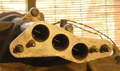
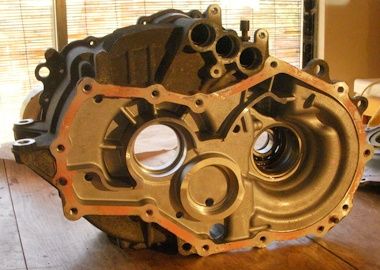
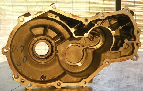
Here is the gearbox side of the system; this is where I figured some improvement could be added.
Here is the gearbox side of the center (stator, etc) section. Not really much to see here, except note that there are pockets for bearings on every shaft, and that there is very little extra room.
Also, there is a potential for an oil fill or cooling oil port directly above the output shaft. You can see the plug bolt in the "top" view next to the breither port (above the power connector in this view) The next views that show the other side of the gearbox will show the oil flow better.
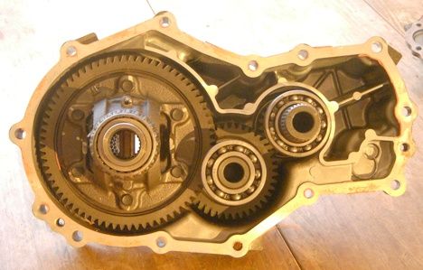
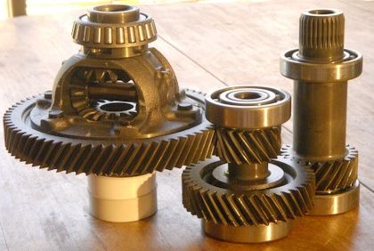
Here is a shot of the gearbox side of the MGR, with the geartrain loosely fit in. In this shot the "oil pump" made by the differential's main gear and the gearbox is visible. Oil is deposited into the containers above the geartrain. While this system is very reliable, there are two problems. 1) You cannot run this motor for any extended time in reverse. It will not get any oil. 2) Oil is used for both lubrication and distributing the heat load. The case and the fins on the case are the only method for getting rid of heat. While this might work ok for standard gearboxes, in this case there is a significant additional load - the motor! To ensure the system reliability, Toyota built into the control a thermal limit measured by sensors in the stator. By doing a better job of cooling the oil, it will be possible to cool the stator more effectively, and thus push the motor harder. 
The gear on the right is the output of the motor, with a splined connection to the rotor. Both the motor rotor and this shaft each have a set of ball bearings on the shaft ends. I think it is made this way so balancing the rotor for 10,500rpm is easier.
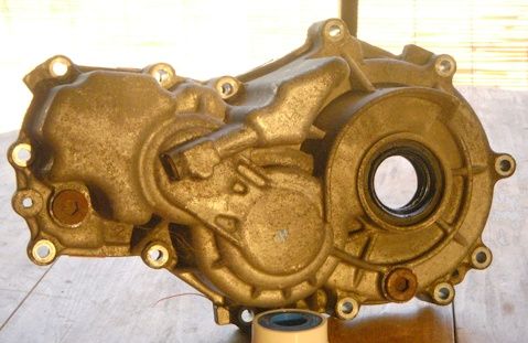
This is the gearbox side without the gears in place. Note the oil passages and specifically the one for the motor. There is a special passage made to deliver oil through the center of the hollow shaft.
The outside of that part. The bearing pockets and oil passages are all easily visible. They didn't spare a bit of metal in making this part! Also note that there is an oil port right where oil is put into the motor's hollow shaft. It may help to add cooled oil directly here.
The gearset. Freebeard's suggestions for polishing and hardening the gears would be a good help. Also, My EVIL plan is to use one of these motors for every wheel. I will need to lock the differentials to do this. Does anyone have ideas for a company that makes custom spools or something like that?
|
|
|
|
|
The Following 2 Users Say Thank You to e*clipse For This Useful Post:
|
|
|


