Oh, boy this brings back memories - of my electric guitar days

Some of my heroes used this information - I did my best to understand modes - to compose some really cool music based in baroque modalities - on the electric guitar. So, it's a bit like actually experiencing Bach on a real church organ. I had pretty much convinced myself that those Organ concerts were the rock concerts of the day. What better way to get folks to come to church?
Anyway... I guess this is lounge stuff .... here's the information I promised a couple of posts back.
The links for the Tamagawa resolvers and the Tamagawa RtoD decoder's application note. If anyone finds themselves trying to get a resolver on Toyota, Ford, or pretty much most newer EV's, including the Leaf, this information is extremely helpful.
Resolver:
http://www.tamagawa-seiki.com/pdf/do.../1570n12ej.pdf
Resolver decoder:
http://www.tamagawa-seiki.com/pdf/do...FT20110708.pdf
Here is what I found running the resolver with a much faster input frequency than it was designed for.
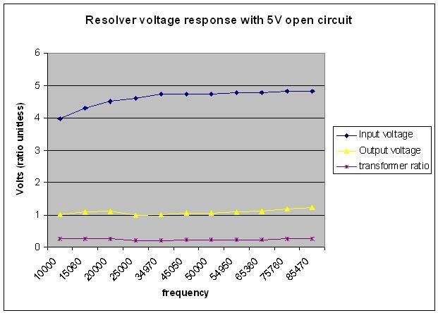
First, the input voltage. I set up my signal generator for a 5V p-p sinusoidal waveform. The "input voltage" is the voltage across the resolver's input at that particular frequency. Note that there is a much greater drop at lower frequncies, and this is a very non-linear response.
The "output voltage" is the voltage measured across the resolver's output through a very simple filter circuit consisting of: resolver > 220 Ohm resistor > 22pF capacitor > 220 Ohm resistor > resolver. The measurements were taken across the capacitor. Note that the actual values of the resistors were 216 Ohms. I experimented with different resistor/capacitor combinations and found the smallest to be most effective in both allowing the signal through and filtering out unwanted noise.
The "transformer ratio" is a number mentioned in the Tamagawa resolver specifications. It's basically the output/input. I tracked that number to see if the response I was getting was close to spec, and if it would change with increased carrier frequency.
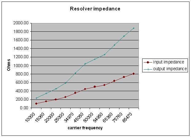
Next I looked into input and output impedance vs carrier frequency. Both of these numbers are calculated, based on Toyota's resistance specifications and Tamagawa's input and output impedance specifications at 10kHz. I first calculated an inductance value for the input and output, based on manufacturer's specifications. I then used the input and output inductance values as a constant to calculate the impedance through the frequency range.
Note that the input impedance appears fairly linear, while the output impedance looks more like some form of curve would fit better. I'm not sure in either case, because measurement error could play heavily in this.

The good news about all this is that it appears that using the 50kHz square wave as a driver will work great.

Also, my test numbers at 10kHz corroborated quite well with the Tamagawa numbers, so these tests look reasonably close. I will probably drive it at a voltage closer to Tamagawa's reccomendation of 7V rms or ~10V p-p. This should result in double the output, or roughly 2V p-p. Amplifying this 2X and offsetting it 2.5V should be no problem.
