 09-07-2014, 01:38 PM
|
#1091 (permalink)
|
|
Permanent Apprentice
Join Date: Jul 2010
Location: norcal oosae
Posts: 523
Thanks: 351
Thanked 318 Times in 215 Posts
|

 I'm glad to see your opinion about interrupts is like mine. I've run across code in app notes that completely relies on interrupts for every little thing to work at all. To me that's scary unreliable.
Hmmm the PIC pin seemed like a great way to provide some synchronization between the resolver and the motor control. - I'm actually not sure at this point if it's entirely necessary - I'll look into that today. I was under the impression from a TI app note that it was necessary to synchronize the AtoD conversions with the resolver. If it's not necessary - or it just needs to be synchronized with itself - then an oscillator IC is a great idea.
BTW, that 40KHz interupt could toggle some unused pin at a perfect - 20kHz - frequency. What is its job?
Also could the FOC frequency be increased? Two reasons 1) The angle between updates at high speed 2) audible noise
Thanks a bunch for all this info. I'm really enjoying this project for that reason alone! 
***edit***Hmmmm that 50KHz signal might be an excellent choice. If there's no 50KHz signal, then the motor drivers aren't running either! I could cut the frequency 50% easily, but that would still be 25kHz. Do you synchronize that signal with the PIC?
***re-edit*** Is that 50KHz signal going to the transformers that bridge to the drivers?
- E*clipse
Quote:
Originally Posted by MPaulHolmes

There's an interrupt that is run only when there's a catastrophe of desaturation detection or undervoltage, so it won't cause any problems with jitter. However, the FOC code is run at 10KHz, and is run inside an interrupt. A 2nd timer based interrupt could do its thing at 40KHz (toggle at 40KHz for 20KHz frequency), but that's a lot of interruptions. I'm not sure how long interrupts take with their pausing and returning. Maybe you could include a little attiny ($1) on the board that oscillates at any frequency that sounds good to you? I use an attiny putting out a frequency of 50KHz (updated at 100kHz) for feeding the inputs of all 6 isolated supply inputs. Fran told me that he used hundreds of attinys in his EVs that he designed (a mine blowing up machine, etc...), and has never seen one be less than 100% reliable.
On the other hand, if you are happy with 50KHz, you could use the signal from the ATTINY that's on the board! haha. Also, the jitter may not cause a problem for the FOC code if we had the main dspic30f4011 do it.
|
Last edited by e*clipse; 09-07-2014 at 02:03 PM..
Reason: thoughts I shoulda had in the first place....
|
|
|

|
 Today Today
|
|
|
|
 Other popular topics in this forum...
|
|
|
|
|
09-07-2014, 07:18 PM
|
#1092 (permalink)
|
|
Permanent Apprentice
Join Date: Jul 2010
Location: norcal oosae
Posts: 523
Thanks: 351
Thanked 318 Times in 215 Posts
|
Ok, answering a bunch of my own questions... 
In reviewing some of my old, notes, it appears that the resolver actually passed higher frequencies BETTER. There is LESS attenuation at a high carrier frequency than a low one. The main advantage of using a low ( 5KHz > 20KHz ) carrier frequency is that the output is more stable. In my tests, there was about a 4.8:1 ratio of input to output at the low frequencies, and about 2:1 ratio between 50KHz > 75KHz. The only downside is that there is more sensitivity to changes in carrier frequency.
However, that 50KHz frequency that's used to drive the driver boards is very stable, so really this is not an issue. So, the best setup would be to buffer the 50KHz with an op-amp (so I don't affect the other users).
A 50KHz carrier frequency also provides really good accuracy for the resolver, because even if the motor is turning at 12,000 rpm, there will still be 62 data points per sine peak.
- E*clipse |
|
|
|
|
The Following User Says Thank You to e*clipse For This Useful Post:
|
|
|
09-08-2014, 12:16 AM
|
#1093 (permalink)
|
|
PaulH
Join Date: Feb 2008
Location: Maricopa, AZ (sort of. Actually outside of town)
Posts: 3,832
Thanks: 1,362
Thanked 1,202 Times in 765 Posts
|
Ya, there are actually 2 pins toggling at 50KHz. When one is low, the other is high. And it's a very stable exact duty of 50%, within maybe 99.999% or something like that. And there are no interrupts or anything. It's just NOPs and a while loop, counted exactly so that the high time and low time are identical cycles, verified in a cycle counting simulator, and also verified on an oscilloscope.
|
|
|
|
|
The Following User Says Thank You to MPaulHolmes For This Useful Post:
|
|
|
09-09-2014, 06:45 PM
|
#1094 (permalink)
|
|
PaulH
Join Date: Feb 2008
Location: Maricopa, AZ (sort of. Actually outside of town)
Posts: 3,832
Thanks: 1,362
Thanked 1,202 Times in 765 Posts
|
Rotor flux angle code is now done!! And it's pretty fast and all C. I don't think I can improve upon it significantly. And I think I actually understand the computations (well, about 95% of it), which is good for debugging. Now the last major part of the code is the space vector modulation. I have to turn Va, Vb, and Vc into PWM duties. I actually already did it a couple years ago, but now I'll rewrite it, and check for errors.
For the last couple days I've been working in the evenings on computing RPM. It sounds pretty straightforward. Count the number of ticks of the encoder during some time interval. I'm using a resolution of [0,3200], where 3200 corresponds to 12000 RPM. That means, the slowest the motor post can spin is 1 revolution every 16 seconds. I had so many different attempts at the fastest possible RPM measuring method. I'm super happy with how it ended up. The ISR is run at 10KHz. The encoder has 2048 ticks per revolution (512 ticks * 4). So, all you have to do inside the ISR is:
Code:
	counter++;
	if (counter >= 78) {  // Compute rpm at 128 times a second.
		revPerSecond_times16 = POSCNT;
		POSCNT = 0;
		counter = 0;
	}
kablammee! No subtractions, no divisions... So pretty. haha. POSCNT is something that's updated automatically. It's the encoder counter. Why 78? Well, 200rev/sec for 1/128 seconds = 200/128 revolutions = 3200 ticks of the encoder. 78 * 0.0001Sec is not actually 1/128. It's 1/128.2. So, this is about 99.9% accurate.
I need to solder those boards, and get the others shipped out! Sorry about the delay. I have excuses though. Our road became a river, and we couldn't drive for the last couple days...
Last edited by MPaulHolmes; 09-09-2014 at 06:53 PM..
|
|
|
|
|
The Following User Says Thank You to MPaulHolmes For This Useful Post:
|
|
|
09-10-2014, 10:32 PM
|
#1095 (permalink)
|
|
PaulH
Join Date: Feb 2008
Location: Maricopa, AZ (sort of. Actually outside of town)
Posts: 3,832
Thanks: 1,362
Thanked 1,202 Times in 765 Posts
|
I've never understood space vector modulation until today. I spent 3:50am until 3pm reading up on it and writing all the details out with pretty graphs, so I never again forget how it works. I was worried about that part. I haven't looked at any sample code. Every stinking detail I finally understand. I am feeling really confident that the code will be very debuggable. I know for sure large parts of it are correct. I am feeling really hopeful. Before, I was thinking that there would be a lot of uncertainty, making debugging difficult.
Edit: I mean I understand the code, and the math details, just not the details about how the motor actually works. Haha.
Last edited by MPaulHolmes; 09-11-2014 at 05:58 AM..
|
|
|
|
|
The Following 2 Users Say Thank You to MPaulHolmes For This Useful Post:
|
|
|
09-11-2014, 03:46 AM
|
#1096 (permalink)
|
|
Permanent Apprentice
Join Date: Jul 2010
Location: norcal oosae
Posts: 523
Thanks: 351
Thanked 318 Times in 215 Posts
|
Awesome!
I'm going to dig through my notes (and Morgan's explanations) to hopefully bring my understanding up to the point I can ask you some reasonable questions...
By the way, I've made a bit of progress on actually understanding my resolver circuits. Funny thing is when I made my first attempt at them, they worked Yea! Except... It was one of those situations where for some reason the kludgy thing works, but you really don't UNDERSTAND why...
The main issue is the resolver driver, which I thought needed to be pretty powerful. After all, I blew up an audio amplifier capable of 3 amps... It seems if you really start to understand impedance, common mode DC, etc, you can get away with something MUCH smaller (cheaper) and reliable.
I got my hands on the data sheet for the resolver and the resolver to digital decoder used by Toyota. There is a TON of good information in those documents. The main limitation that I've found is the carrier signal is targeted at 10kHz. What happens if we drive it 5 times faster??
To find out, I ran a series of tests from 10kHz to 85kHz and measured the input voltage, output voltage and calculated the input and output impedance and transformer ratio for every data point.
The good news is that the input and output impedance actually increase proportionally to the carrier frequency. At the same time the transformer ratio stays relatively constant. Why is this good? For a given voltage, the higher frequency will require less power.
I'll post some links and pretty graphs soon.
- E*clipse |
|
|
|
|
The Following 2 Users Say Thank You to e*clipse For This Useful Post:
|
|
|
09-11-2014, 01:28 PM
|
#1097 (permalink)
|
|
Master EcoModder
Join Date: Aug 2012
Location: northwest of normal
Posts: 29,440
Thanks: 8,378
Thanked 9,132 Times in 7,540 Posts
|
No pressure, but I'm betting the farm on you guys pulling this off. 
I studied TV servicing in the 1970s, but at this point I couldn't get much beyond the 'like water in a hose' analogy. But I discovered Eric P. Dollard's so now I know about Maxwell, Heavyside and Steinmetz and how the dielectric is as important as the conductor. I don't want to dissipate the momentum you have built up, but I wonder if Versor Algebra might be helpful, since:
Quote:
|
It should be noted that Nikola Teslas original archetypal vision of alternate electric waves was his poetic versor rotation of the Sun-Earth relation. Needless to say versor algebra finds extensive application in alternating current theory. Read first part Symmetrical Components by Wagner and Power and Double Frequency Quantities by Steinmetz, (from his A.C. book), for advanced concepts.
|
|
|
|
|
|
The Following 2 Users Say Thank You to freebeard For This Useful Post:
|
|
|
09-11-2014, 03:17 PM
|
#1098 (permalink)
|
|
Permanent Apprentice
Join Date: Jul 2010
Location: norcal oosae
Posts: 523
Thanks: 351
Thanked 318 Times in 215 Posts
|
Ouch! I think my head's going to explode!
And I was just re-learning the EE-101 stuff I had successfully managed to ignore all these years...
Well, since I still have a head (I think )and also have this controller and the much more linear issues like "how to package and manage the lithium-ion batteries", I'm going to bookmark Versers for much later (years) reading... |
|
|
|
|
09-11-2014, 05:28 PM
|
#1099 (permalink)
|
|
Master EcoModder
Join Date: Aug 2012
Location: northwest of normal
Posts: 29,440
Thanks: 8,378
Thanked 9,132 Times in 7,540 Posts
|
Yeah, I recommend that. But for off-hours entertainment the first 50 minutes is great. He personalizes historic figures. Morse was a painter, Edison was a telegraph operator and Steinmetzwhoa, he was a radical pamphleteer in 1915 Berlin.
Also seek out his story about *Experiencing* Bach in the Grace Cathedral in SF during the Harmonic Convergence. It was originally on Youtube as 'Eric Dollard Talks Bach, Tesla and The Church Organ' but he's apparently got an entity 'AetherForce' throwing ad hominem attacks at him. Try this podcast [...youtube...watch?v=W_DiYxrJMzA] Eric P Dollard - The Supernatural Power of Music
Then back to work. |
|
|
|
|
09-11-2014, 07:42 PM
|
#1100 (permalink)
|
|
Permanent Apprentice
Join Date: Jul 2010
Location: norcal oosae
Posts: 523
Thanks: 351
Thanked 318 Times in 215 Posts
|
Oh, boy this brings back memories - of my electric guitar days Some of my heroes used this information - I did my best to understand modes - to compose some really cool music based in baroque modalities - on the electric guitar. So, it's a bit like actually experiencing Bach on a real church organ. I had pretty much convinced myself that those Organ concerts were the rock concerts of the day. What better way to get folks to come to church?
Anyway... I guess this is lounge stuff .... here's the information I promised a couple of posts back.
The links for the Tamagawa resolvers and the Tamagawa RtoD decoder's application note. If anyone finds themselves trying to get a resolver on Toyota, Ford, or pretty much most newer EV's, including the Leaf, this information is extremely helpful.
Resolver:
http://www.tamagawa-seiki.com/pdf/do.../1570n12ej.pdf
Resolver decoder:
http://www.tamagawa-seiki.com/pdf/do...FT20110708.pdf
Here is what I found running the resolver with a much faster input frequency than it was designed for.
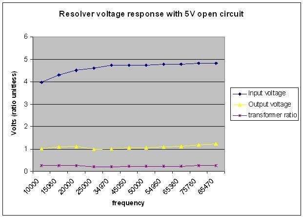
First, the input voltage. I set up my signal generator for a 5V p-p sinusoidal waveform. The "input voltage" is the voltage across the resolver's input at that particular frequency. Note that there is a much greater drop at lower frequncies, and this is a very non-linear response.
The "output voltage" is the voltage measured across the resolver's output through a very simple filter circuit consisting of: resolver > 220 Ohm resistor > 22pF capacitor > 220 Ohm resistor > resolver. The measurements were taken across the capacitor. Note that the actual values of the resistors were 216 Ohms. I experimented with different resistor/capacitor combinations and found the smallest to be most effective in both allowing the signal through and filtering out unwanted noise.
The "transformer ratio" is a number mentioned in the Tamagawa resolver specifications. It's basically the output/input. I tracked that number to see if the response I was getting was close to spec, and if it would change with increased carrier frequency.
Next I looked into input and output impedance vs carrier frequency. Both of these numbers are calculated, based on Toyota's resistance specifications and Tamagawa's input and output impedance specifications at 10kHz. I first calculated an inductance value for the input and output, based on manufacturer's specifications. I then used the input and output inductance values as a constant to calculate the impedance through the frequency range.
Note that the input impedance appears fairly linear, while the output impedance looks more like some form of curve would fit better. I'm not sure in either case, because measurement error could play heavily in this. 
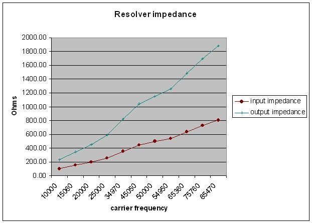
The good news about all this is that it appears that using the 50kHz square wave as a driver will work great. Also, my test numbers at 10kHz corroborated quite well with the Tamagawa numbers, so these tests look reasonably close. I will probably drive it at a voltage closer to Tamagawa's reccomendation of 7V rms or ~10V p-p. This should result in double the output, or roughly 2V p-p. Amplifying this 2X and offsetting it 2.5V should be no problem.
|
|
|
|
|
The Following User Says Thank You to e*clipse For This Useful Post:
|
|
|


