OK, J6 is for powering the main contactor coil.
J5 is for powering the precharge relay coil (J5 is NOT the precharge relay, just for powering the precharge relay coil. The precharge relay must exist somewhere off the board).
J4 is the +24v power. The right pin is +24v. The left pin is ground.
J3 is the valet mode option. But the controller is so dang smooth, that you may not need it! haha
The 5 wire ribbon cable is for reprogramming the microcontroller with the pickit3.
With the big cables facing you, the 3 long cables all get connected to M+ (motor plus). The 2 cables close together on the left are B+, and must be connected to the battery pack b+ (through a contactor/fuse etc...)
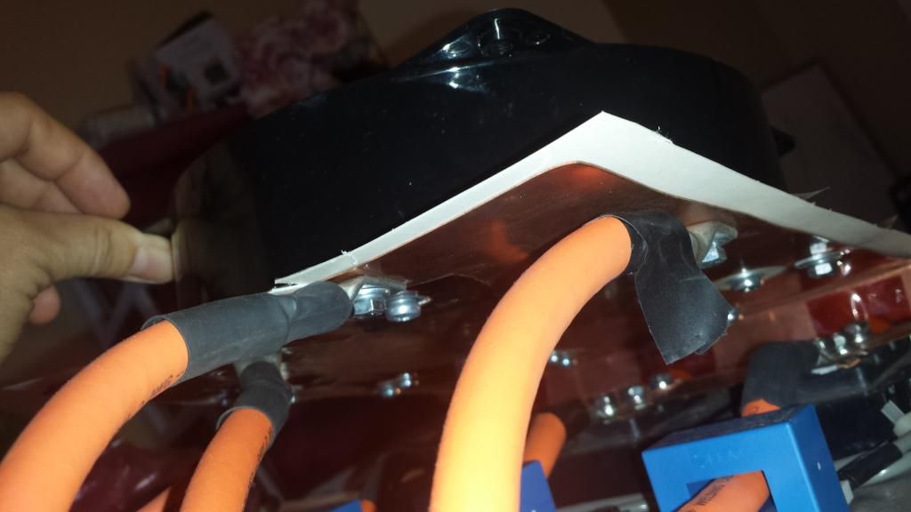
The 2 cables close together on the right are B-, and must be connected to the battery pack B-, AND ALSO M-. Well, I'm pretty sure that's how I did B+ and B-. You may want to check that it looks like this:
RIGHT SIDE IS B- IN THIS PICTURE (notice where the cables are connected):