Quote:
Originally Posted by MPaulHolmes

Could you post a picture of the layout and where the connector is? That would help me get the creative juices flowing. haha
cts_casemod: I have 1 more board, but I was going to populate it for testing. The other 4 boards are prototypes of people on here. Also, it's going to need a revision, so I'll have to order more once we figure out what needs changing.
|
I'm willing to work/test on that for you, if you can share the schematics and any other relevant information. I will also write a report on my setup by August next year.
I need to design a gate driver that can do two functions:
- Power a vehicle with the usual 200-600Amps IGBT's (3Ph)
- Serve as a test bench for my small experiences such as sine wave inverters, etc.
That generally means the design of the DC-Link as well.
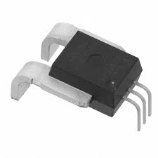
For the small model, obviously I am looking at building everything on a PCB, using hall sensors like these.
This will include a 1Ph/3Ph PFC charger I am working on now (anyone here concentrating on charger development?)
This is for IGBT's rated 600V @ 40Amps.
For the larger model, something like this:

Notice the board on the left is a single phase PFC charger. Its set to charge at 1.5KW/440V. I have two.