Quote:
Originally Posted by MPaulHolmes

Could you post a picture of the layout and where the connector is? That would help me get the creative juices flowing. haha
cts_casemod: I have 1 more board, but I was going to populate it for testing. The other 4 boards are prototypes of people on here. Also, it's going to need a revision, so I'll have to order more once we figure out what needs changing.
|
Hi Paul!
Here's a pic of the board:
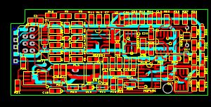
The five pin SIL connector is on the bottom of the board and fits the QEI connector. Because of the fastening issues, it would be nice to find a latching board-board connector.

The 8 pin connector right next to it is on top, and is a latching flat-ribbon wire connector, designed for standard 0.05" spaced wires. I figure eventually this controller will be in some form of box, where it can connect to a shielded cable. I have an 8 connector shielded wire to see how that will work out. There are 3 pairs of wires for the resolver, and two for the motor's thermistor. The motor's thermistor connects to the QEI index pin.
The two pin connector is a latching connector for the +24V supply.
The notch on the upper left of the board is clearance for the POT connector.
Right now there is one bolt hole, on the bottom right of the board. There is no other place on the motor controller to put a hole. I probably could shuffle stuff around more to make space for a second hole right above it.
OK - requests for the second rev controller board:
1) Provisions for a latching QEI connector - I haven't found one yet.
2) Provisions for a second fastening hole for the resolver board
3) Some way to seperate the driver boards from the controller board to allow IGBT versatility.
Please - anyone - RIP on this board - I would much rather hear of it's issues now, then when it's done.
My biggest concern is noise. This board will sit right over the microprocessor and the microprocessor's timing crystal. Also, it will have it's own noise generator, a 50kHz oscillator.
If anyone has had any experience with these interactions, I would love to here it. Also, on the lower left side of the board is the output amplifier. It was designed for about 2 sq. inches of bare copper to act as a heat sink. I obviously don't have that, and need to come up with some decent alternative.
E*clipse