Quote:
Originally Posted by freebeard

Thee Template is more or less a guideline, as it assumes a half-circular cross-section. Taper in plan and tumblehome affect the result (see the GM EV-1). You can't even trust tufts completely, but Toyota seem to know what they're doing.
|
Something else I see missing around here...
AST (I or II) ≠ attached flow ≠ ideal
That is, just because there is attached flow, doesn't make a shape ideal. And you don't have to follow the template for attached flow.
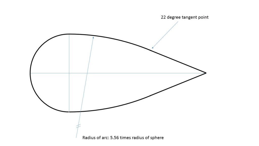
I did some playing a bit ago with the template. As an engineer (being nothing more than a cup of coffee and a spreadsheet) I fired up Excel. Plotted and fussed with the template. I arrived at this:

At this point, the math/numbers are irrelevant. It let me draw the template shape (in 2D obviously).
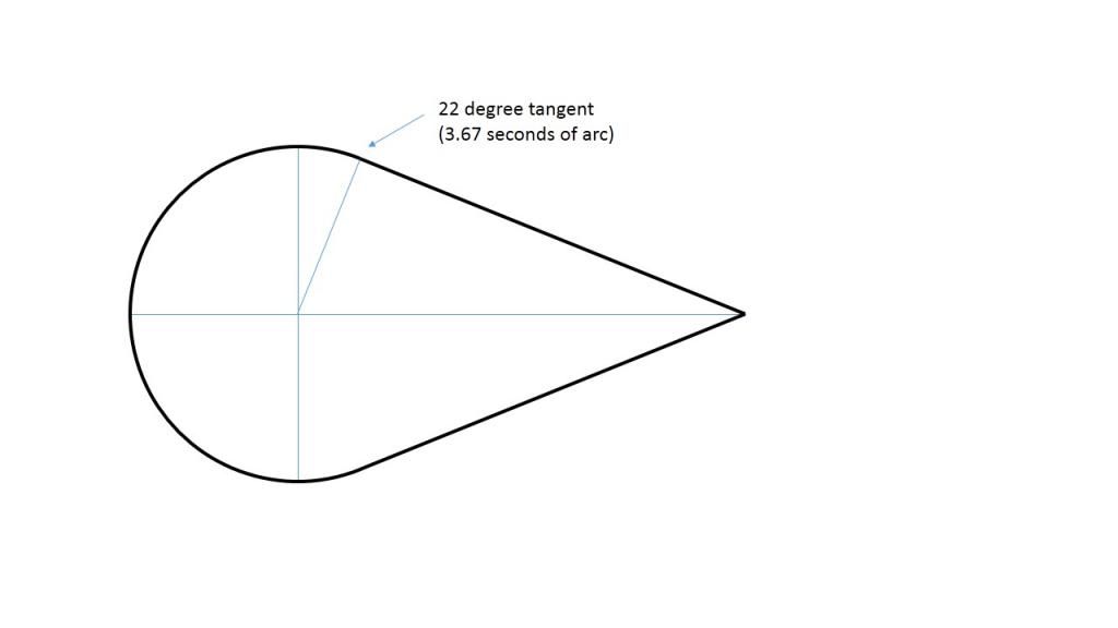
We know that a sphere in a wind tunnel has attached flow for a few degrees past tangent. It's often expressed as 3 or 4 seconds on the clock face. Knowing that, and recalling the oft mentioned 22° (as happens to be found on "the template" too.) I drew this:

What do you know, 22° lands at 3.67 seconds. Hmmm....
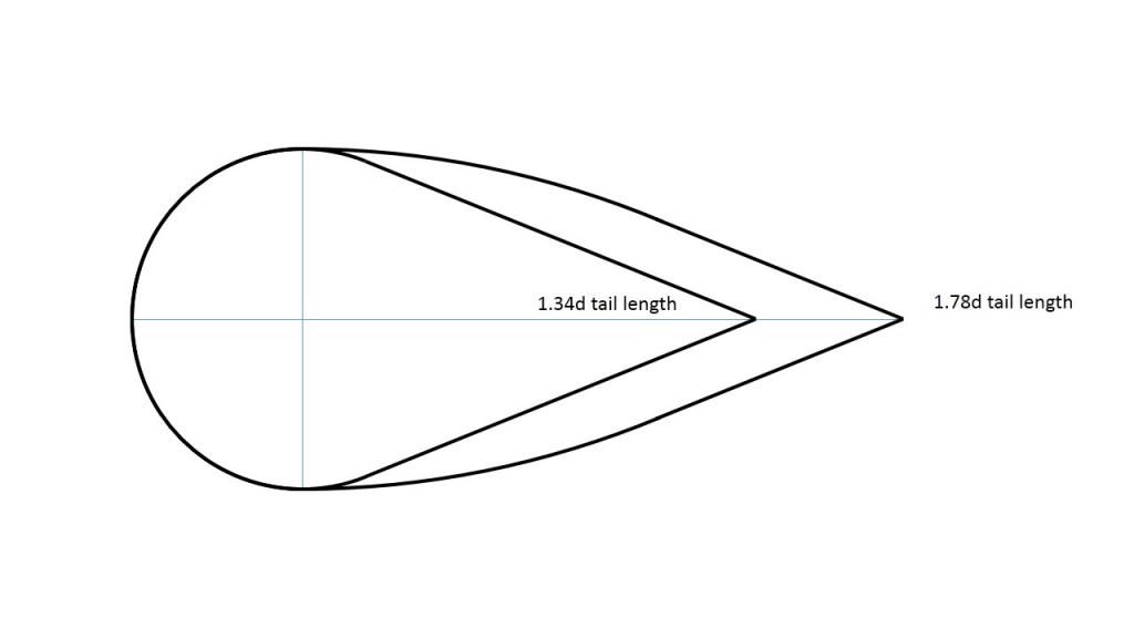
Is this second shape a "minimum" shape to achieve attached flow? Data I've seen suggest it is. Or at least very close. Would this shape be ideal? No, we already know that. But, it ends up pretty close to the template, and perhaps explains why many "less than ideal" tails do so well. Here they are together:

Not all that different.
SO.
Less than ideal tail for a Prius, that follows the Toyota lines? It'll be less than ideal, but very good chance it'll exhibit attached flow.