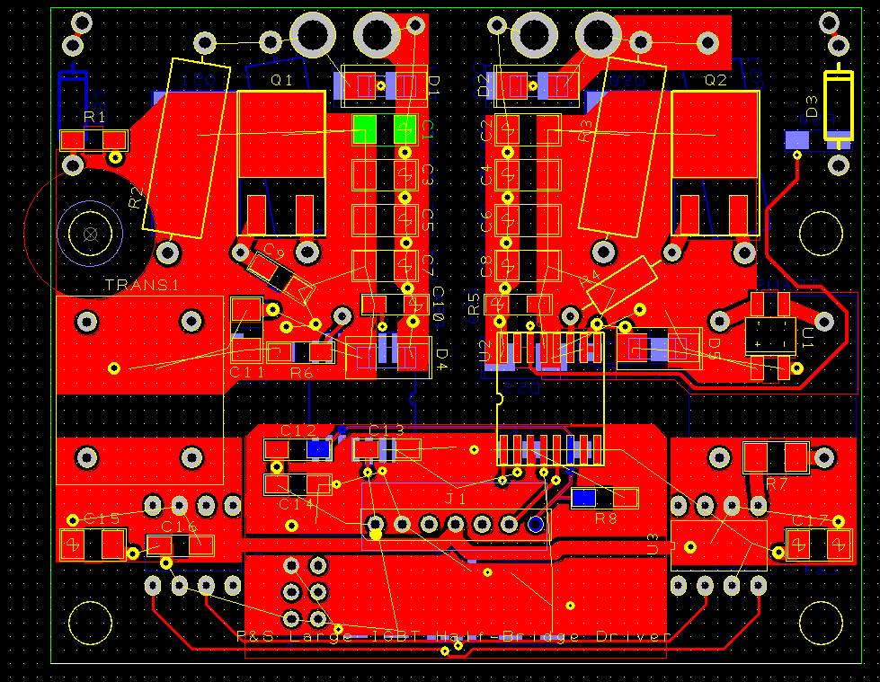
I just finally finished and submitted a basic stand-alone dual IGBT driver board, which has a 7 pin connector for +24v, ground, +5v, pwm high, pwm low, desat fault, clear desat. You can use it to drive very large IGBTs (I've tested the circuit on a 600v 600amp IGBT at 10KHz already). It Just plugs into the IGBT.
You can use it as a high side or low side driver for a dc controller too. I added a couple extra holes so you could short out the low side (or high side) gate to emitter so the 2nd IGBT could act as the freewheel diode. I think I'll sell them for maybe $7 each for those that want to make their own 3 phase inverter or dc controller, but don't want to mess with making their own high power driver section. I would like to buy bulk parts so they could be cheap to populate too.
The current required for the pwm input signals is teeny tiny (way way less than a milliamp), so you could drive it with just about anything.
They are 3.04" x 2.46". Here's a picture of it:

The main reason I made it was so I could add a basic ATTINY to the 3 phase control board that would just have a fixed PWM duty (high and low side). Then I could use that driver board as a part of a boost stage for the inverter. e*clipse bought me a super fancy 650v motor, so I'm going to go from theory to practice very soon! Maybe a 200v pack, boosted to 650v or whatever.
EDIT: crap, I had the bottom copper layer blocked out in the picture I attached. oh well.