 02-07-2015, 11:38 PM
|
#1681 (permalink)
|
|
Master EcoModder
Join Date: Sep 2010
Location: Saskatoon, canada
Posts: 1,488
Thanks: 746
Thanked 565 Times in 447 Posts
|
Quote:
Originally Posted by MPaulHolmes

The 2 gauge cable is a pretty tight fit, but a cable tie wouldn't be a bad idea.
|
After taking off the cover and looking at the current sensors ... my initial idea is way off base!
Keeping the sensors from sliding around would be nice. I'll try some cable ties if I can get my fingers in there.
|
|
|

|
|
The Following User Says Thank You to thingstodo For This Useful Post:
|
|
 Today Today
|
|
|
|
 Other popular topics in this forum...
|
|
|
|
|
02-08-2015, 01:21 AM
|
#1682 (permalink)
|
|
Master EcoModder
Join Date: Sep 2010
Location: Saskatoon, canada
Posts: 1,488
Thanks: 746
Thanked 565 Times in 447 Posts
|
Quote:
Originally Posted by thingstodo
I received and unpacked to controller tonight
Pictures to follow. A screw terminal fell out of the controller when I picked it up so I guess I'll be doing some reading tomorrow, take the controller apart, and verify a couple of things
|
Unpacking
Box 67
Popcorn! Yay! 68
Bubble wrap and electrical tape 69
The controller with the cable glands, terminal blocks 70
The controller on the low voltage side 71
The controller on the high voltage side 72
The displaced screw that is causing all the trouble 73
The 2 extra screws Paul shipped 74 |
|
|
|
|
The Following User Says Thank You to thingstodo For This Useful Post:
|
|
|
02-08-2015, 01:26 AM
|
#1683 (permalink)
|
|
Master EcoModder
Join Date: Sep 2010
Location: Saskatoon, canada
Posts: 1,488
Thanks: 746
Thanked 565 Times in 447 Posts
|
Investigation
The search for where the screw, or perhaps terminal screw, that fell out of the controller should be re-installed ..
Pop off the cover - 4 bolts for the capacitor, 2 more for the DC/DC power supply, and like .. 10 .. for the case to the heat sink.
High voltage side 77
Controller board 78
Beautiful control board. Nicely done Paul! But the control board is not missing any screws.
The capacitors have all fasteners in place. Same with the IGBTs. Look over the heat sink and the case ... nothing missing.
Controller and signals 79
Controller again 80
Current sensors view 1 81
Current sensors view 2 82
Aiming up above current sensors 83
Current sensors last one 84
Go over the case again. I moved the DC/DC converter and .. noticed that there is one screw missing! The home of the offending screw has been found!
|
|
|
|
|
The Following 3 Users Say Thank You to thingstodo For This Useful Post:
|
|
|
02-08-2015, 10:16 AM
|
#1684 (permalink)
|
|
PaulH
Join Date: Feb 2008
Location: Maricopa, AZ (sort of. Actually outside of town)
Posts: 3,832
Thanks: 1,362
Thanked 1,202 Times in 765 Posts
|
The DC-DC has 2 spots (maybe 3 if you count a screw spot) where you can screw in M3 screws (no nut required). But that would require a couple extra holes in the enclosure. Now that I know the screw came out in shipping, I think it would be a good idea to use those extra 2 screw holes (and the 3rd hole too if you want). You don't need a full 50w DC-DC. It's just that the 15 or 20w versions were out of stock. Those are smaller and lighter. Oh well.
|
|
|
|
|
The Following User Says Thank You to MPaulHolmes For This Useful Post:
|
|
|
02-12-2015, 10:13 PM
|
#1685 (permalink)
|
|
Master EcoModder
Join Date: Sep 2010
Location: Saskatoon, canada
Posts: 1,488
Thanks: 746
Thanked 565 Times in 447 Posts
|
No progress until Feb 15
I've been busy with other things - should be able to power it up on Sunday, but first I need to:
- get the contactors connected
- get a 48V battery pack and precharge resistor connected
- get my test 5 HP motor connected
- make a bushing to fit my encoder to the motor shaft
- get it all connected up
|
|
|
|
|
The Following 2 Users Say Thank You to thingstodo For This Useful Post:
|
|
|
02-12-2015, 10:44 PM
|
#1686 (permalink)
|
|
PaulH
Join Date: Feb 2008
Location: Maricopa, AZ (sort of. Actually outside of town)
Posts: 3,832
Thanks: 1,362
Thanked 1,202 Times in 765 Posts
|
Phew! I've been busy too. I'm just glad I wasn't holding you up. I'm not in a hurry, so don't feel any pressure on my end. But I'll try to get the PI loop tuning code done by this weekend too.
|
|
|
|
|
The Following 2 Users Say Thank You to MPaulHolmes For This Useful Post:
|
|
|
02-14-2015, 08:01 PM
|
#1687 (permalink)
|
|
PaulH
Join Date: Feb 2008
Location: Maricopa, AZ (sort of. Actually outside of town)
Posts: 3,832
Thanks: 1,362
Thanked 1,202 Times in 765 Posts
|
I just finally finished and submitted a basic stand-alone dual IGBT driver board, which has a 7 pin connector for +24v, ground, +5v, pwm high, pwm low, desat fault, clear desat. You can use it to drive very large IGBTs (I've tested the circuit on a 600v 600amp IGBT at 10KHz already). It Just plugs into the IGBT.
You can use it as a high side or low side driver for a dc controller too. I added a couple extra holes so you could short out the low side (or high side) gate to emitter so the 2nd IGBT could act as the freewheel diode. I think I'll sell them for maybe $7 each for those that want to make their own 3 phase inverter or dc controller, but don't want to mess with making their own high power driver section. I would like to buy bulk parts so they could be cheap to populate too.
The current required for the pwm input signals is teeny tiny (way way less than a milliamp), so you could drive it with just about anything.
They are 3.04" x 2.46". Here's a picture of it:
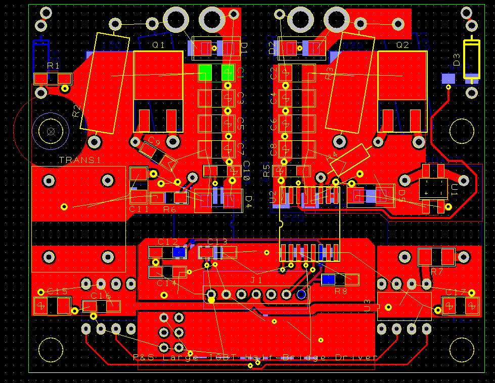
The main reason I made it was so I could add a basic ATTINY to the 3 phase control board that would just have a fixed PWM duty (high and low side). Then I could use that driver board as a part of a boost stage for the inverter. e*clipse bought me a super fancy 650v motor, so I'm going to go from theory to practice very soon! Maybe a 200v pack, boosted to 650v or whatever.
EDIT: crap, I had the bottom copper layer blocked out in the picture I attached. oh well. |
|
|
|
|
The Following 3 Users Say Thank You to MPaulHolmes For This Useful Post:
|
|
|
02-14-2015, 08:27 PM
|
#1688 (permalink)
|
|
Master EcoModder
Join Date: Sep 2010
Location: Saskatoon, canada
Posts: 1,488
Thanks: 746
Thanked 565 Times in 447 Posts
|
Quote:
Originally Posted by MPaulHolmes
I just finally finished and submitted a basic stand-alone dual IGBT driver board, which has a 7 pin connector for +24v, ground, +5v, pwm high, pwm low, desat fault, clear desat. You can use it to drive very large IGBTs (I've tested the circuit on a 600v 600amp IGBT at 10KHz already). It Just plugs into the IGBT.
You can use it as a high side or low side driver for a dc controller too. I added a couple extra holes so you could short out the low side (or high side) gate to emitter so the 2nd IGBT could act as the freewheel diode. I think I'll sell them for maybe $7 each for those that want to make their own 3 phase inverter or dc controller, but don't want to mess with making their own high power driver section. I would like to buy bulk parts so they could be cheap to populate too.
|
AWESOME!
First - Do you need any beta testers or have you past that phase already?
Second - What are your price breakpoints? I likely won't have time to build more than 4 or 5 of them, but I can order a couple dozen boards .. maybe more?
Background story/boring stuff
I have several (many?) retired/surplus industrial VFDs that I would like to upcycle. The smallest is 6 amps at 575VAC and the largest is 400 amps at 575VAC. Some have IGBTs failed, some have capacitors failed, some are likely in operational condition but the keypad/user interface is not operational (and is required to use it)
All of these units are awaiting brain transplants so that they can become battery chargers, DC controllers, AC controllers, battery dischargers, DC buck/boost controllers ... you get the idea.
The DC bus is in place, spaced correctly for the voltage. The heat sinks are in place and the IGBTs mounted. I need to replace the controller board(s), add a master controller to generate the signals, and another to handle the outside world (throttle, brakes, line voltage synchronizing, CANbus).
Still a bit of a hurdle, that will take some time, but not such a big hurdle now that you've done the heavy lifting of creating the driver board! |
|
|
|
|
02-14-2015, 09:33 PM
|
#1689 (permalink)
|
|
Permanent Apprentice
Join Date: Jul 2010
Location: norcal oosae
Posts: 523
Thanks: 351
Thanked 318 Times in 215 Posts
|
That's awesome Paul!
It would really help for my ring-cap based controller design! 
BTW, do you have any idea how the distance between the PWM control signal start and the input to this might affect issues like noise or timing issues?
I'm assuming a twisted pair wire that might be several inches long.
Oh, yes, I will definitely be looking at about 12+ of these.
Thanks a bunch,
E*clipse |
|
|
|
|
02-14-2015, 09:38 PM
|
#1690 (permalink)
|
|
Permanent Apprentice
Join Date: Jul 2010
Location: norcal oosae
Posts: 523
Thanks: 351
Thanked 318 Times in 215 Posts
|
Are any of those VFD's in working condition?
If so, would you be willing to let a couple go as-is?
I'm looking for better ways to control my mill & lathe speeds; something in the range of 3hp to 5hp, 240V single phase.
Since this is totally OT, PM me if it's possible. 
- E*clipse
Quote:
Originally Posted by thingstodo
AWESOME!
Background story/boring stuff
I have several (many?) retired/surplus industrial VFDs that I would like to upcycle. The smallest is 6 amps at 575VAC and the largest is 400 amps at 575VAC. Some have IGBTs failed, some have capacitors failed, some are likely in operational condition but the keypad/user interface is not operational (and is required to use it)
|
|
|
|
|
|


