Quote:
Originally Posted by thingstodo

High V side
Battery pack neg -> precharge resistor (with precharge contactor across it) -> B- on controller
Battery pack pos -> 80 amp DC braker -> primary contactor -> B+ on controller
|
thingstodo, i am not sure about the pre charge contactor set up you have described.
I had a quick look at Pauls code and it looks like the pre charge voltage is turned on, then after a 1 second delay the main contactor voltage is turned on. But then, after a further delay of 0.2 seconds the pre charge contactor voltage is removed.
This seems designed to work with something like circuit 2 below whereas your description sounds more like circuit 1.
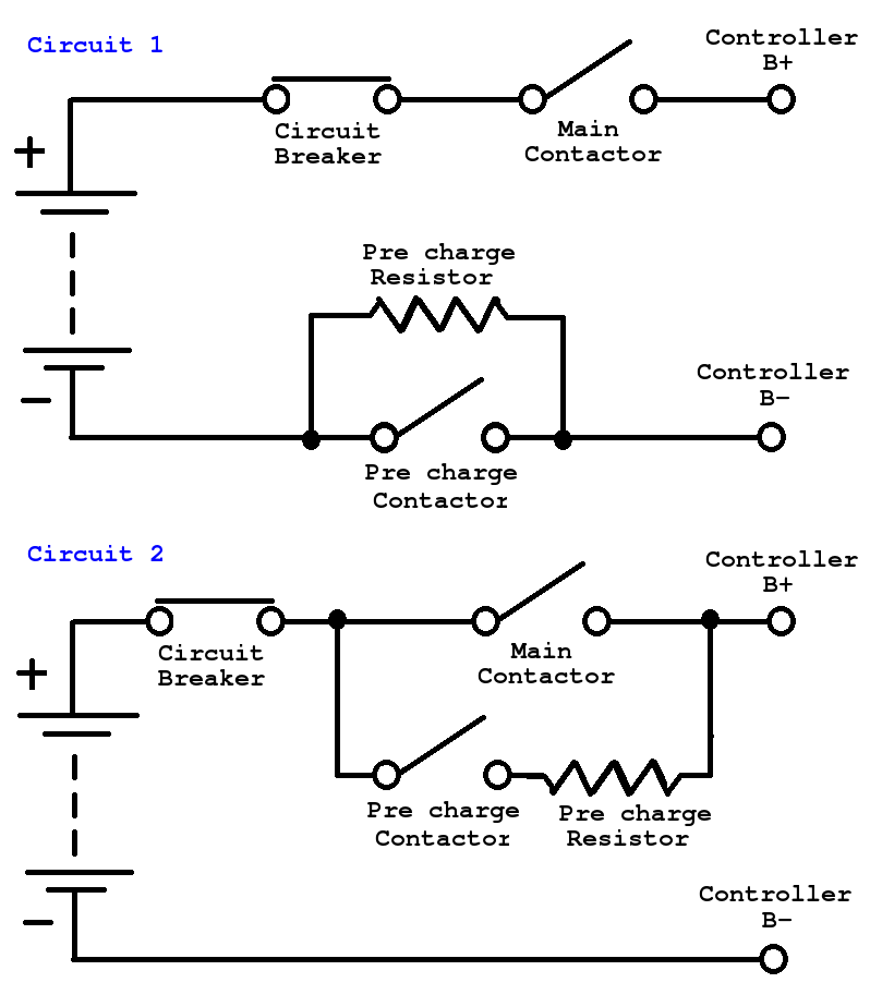
Circuit 1 would require the main contactor close first. Controller charges through pre charge resistor. Then the pre charge contactor is closed and the main contactor stays closed. Both contactors must stay closed whilst the controller is driving the motor.
Circuit 2 has the pre charge contactor closing first. Controller charges. Then the main contactor closes. The pre charge contactor is now bypassed by the main contactor and so can be de energised (opened). Only the main contactor needs to remain closed while the controller is driving the motor.
If you have already wired your vehicle then the start up sequence could be changed in the controller software.
Remove the two lines that cause the pre charge contactor to open.
And swap the main and pre charge variables.
Before changes
Code:
    O_LAT_PRECHARGE_RELAY = 1;  // 1 means close the relay.  Now the cap is filling up.
    DelayTenthsSecond(10); // savedValues.prechargeTime);

    // High pedal lockout. Wait until they aren't touching the throttle before closing the main contactor.
    do {
        ReadADInputs();
    } while (ADThrottle < savedValues.minRegenPosition || ADThrottle > savedValues.minThrottlePosition);  // I'm using a wig wag hall effect throttle.

    O_LAT_CONTACTOR = 1;    // close main contactor.
    DelayTenthsSecond(2);   // delay 0.2 seconds, to give the contactor a chance to close.  Then, there will be no current going through the precharge relay.
    O_LAT_PRECHARGE_RELAY = 0;  // open precharge relay once main contactor is closed.
After changes
Code:
    O_LAT_CONTACTOR = 1;  // 1 means close the main relay.  Now the cap is filling up.
    DelayTenthsSecond(10); // savedValues.prechargeTime);

    // High pedal lockout. Wait until they aren't touching the throttle before closing the main contactor.
    do {
        ReadADInputs();
    } while (ADThrottle < savedValues.minRegenPosition || ADThrottle > savedValues.minThrottlePosition);  // I'm using a wig wag hall effect throttle.

    O_LAT_PRECHARGE_RELAY = 1;    // close precharge contactor.
//    DelayTenthsSecond(2);   // delay 0.2 seconds, to give the contactor a chance to close.  Then, there will be no current going through the precharge relay.
//    O_LAT_PRECHARGE_RELAY = 0;  // open precharge relay once main contactor is closed.
A disadvantage to running with a precharge circuit like circuit 1 is that both the pre charge and main contactors must be rated to carry the full traction current. Whereas with circuit 2 the pre charge only has to carry a fraction of the current and only for 1 second. So the pre charge contactor can be a much lower cost device.