 02-17-2015, 11:50 PM
|
#1721 (permalink)
|
|
PaulH
Join Date: Feb 2008
Location: Maricopa, AZ (sort of. Actually outside of town)
Posts: 3,832
Thanks: 1,362
Thanked 1,202 Times in 765 Posts
|
the largest current is probably 50mA on the 7 wires. wouldnt 20 gauge be OK for that?
|
|
|

|
 Today Today
|
|
|
|
 Other popular topics in this forum...
|
|
|
|
|
02-18-2015, 06:48 AM
|
#1722 (permalink)
|
|
Dreamer
Join Date: Nov 2013
Location: Australia
Posts: 350
Thanks: 95
Thanked 214 Times in 151 Posts
|
Quote:
Originally Posted by MPaulHolmes

I just finally finished and submitted a basic stand-alone dual IGBT driver board, which has a 7 pin connector for +24v, ground, +5v, pwm high, pwm low, desat fault, clear desat. You can use it to drive very large IGBTs (I've tested the circuit on a 600v 600amp IGBT at 10KHz already). It Just plugs into the IGBT.
|
I think this module is going to inspire a lot of other projects.
You have done the hard bit for most people.
Well done.
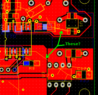
I have to ask though. On many of these layout images i keep seeing something that confuses me. I can see the components are shown for both sides and the copper traces. But then there are these thin yellow lines that seem to connect different components but sometimes they seem to stop where there are no components. Is this showing connections "as the crow flies" rather than routed? They sort of look like those Nazca lines in Peru. 
|
|
|
|
|
The Following User Says Thank You to Astro For This Useful Post:
|
|
|
02-18-2015, 11:24 AM
|
#1723 (permalink)
|
|
Master EcoModder
Join Date: Sep 2010
Location: Saskatoon, canada
Posts: 1,488
Thanks: 746
Thanked 565 Times in 447 Posts
|
Quote:
Originally Posted by e*clipse
Another problem I'm working on uses differential pair signalling. In this case, I understand a twisted pair cable is the best solution, but I'm not sure how a shield or ground surface plays into it. Thingstodo - could you ask about differential pair signals? Any advice from the instrument supervisor would be invaluable.  |
I forgot to ask about the differential pair thing yesterday.
Today's info - put the differential signal on a single pair to get the most benefit from the shield. The rest of the stuff about shields applies
As for the gauge, #18 was to allow our HART signals to go 2500 feet (!!) with OK losses for signal based on resistance. For short runs almost any gauge will do as long as the cable is stranded. There is no RIGHT and WRONG, more like Better and OK. |
|
|
|
|
The Following 2 Users Say Thank You to thingstodo For This Useful Post:
|
|
|
02-18-2015, 11:34 AM
|
#1724 (permalink)
|
|
Master EcoModder
Join Date: Sep 2010
Location: Saskatoon, canada
Posts: 1,488
Thanks: 746
Thanked 565 Times in 447 Posts
|
ME labs programmer instead of PICkit3
I thought I had posted this a while ago ... but I don't see my post or any responses .. my attention span is really suffering lately!
I have an old ME labs U2 USB programmer (circa 2004) that I'm told *SHOULD* work with ICSP. My stepson had used it for a university engineering project ... that somehow I don't remember. He put the PIC chips into the ZIF socket to program them, then inserted them into his board so he did not use ICSP.
Here is a link to the support page microEngineering Labs, Inc. | 1-719-520-5323 | In Circuit Serial Programming with EPIC
My question is:
- Can I use the DC/DC converter and it's 24V supply to the controller board to power up the dsPIC30F2010 but use the rest of the signals from the programmer on the ICSP header?
I don't want to blow up 1 of the 2 prototypes with a dumb mistake!
If I need to buy a PICkit 3, it's not a big deal. Just a bit of delay. |
|
|
|
|
02-18-2015, 12:12 PM
|
#1725 (permalink)
|
|
PaulH
Join Date: Feb 2008
Location: Maricopa, AZ (sort of. Actually outside of town)
Posts: 3,832
Thanks: 1,362
Thanked 1,202 Times in 765 Posts
|
Astro: Oh those thin yellow lines are the helpful reminder by the program that I forgot to connect various points on the board that should be connected by copper. They are showing up because I had cleared the copper ground plane earlier before I took that screen shot, so all the points that were connected to ground were no longer connected to each other.
thingstodo: It looks like the 5 pins that are needed on the ISP connector are also on that programmer, I think. I'm a little confused by some of them though. I'm not sure if Vpp functions the same as the MCLR pin on the board. The pinout on the board ISP is:
PIN 1: MCLR
PIN 2: +5V
PIN 3: GROUND
PIN 4: PGD
PIN 5: PGC
PIN 6: UNUSED
So maybe if you just match all those, it should be fine? What I always do is, plug the USB end of the programmer into my computer, and then plug the other end into the board, and then turn on the +24v power to the board, which provides the +5v to the programmer. I'm sure that would be how your programmer would work too.
I'm not sure if mplab will recognize the programmer. You have to select it from a drop-down list. So you would have to probably program the hex file using a different program.
|
|
|
|
|
02-18-2015, 12:42 PM
|
#1726 (permalink)
|
|
Master EcoModder
Join Date: Sep 2010
Location: Saskatoon, canada
Posts: 1,488
Thanks: 746
Thanked 565 Times in 447 Posts
|
Quote:
Originally Posted by MPaulHolmes
thingstodo: It looks like the 5 pins that are needed on the ISP connector are also on that programmer, I think. I'm a little confused by some of them though. I'm not sure if Vpp functions the same as the MCLR pin on the board. The pinout on the board ISP is:
PIN 1: MCLR
PIN 2: +5V
PIN 3: GROUND
PIN 4: PGD
PIN 5: PGC
PIN 6: UNUSED
So maybe if you just match all those, it should be fine?
|
Driving Pins 1,3,4,5 is fine and match up. Pin 2 - the 5V - has a warning that it can't supply much power so that's why I asked about powering up the board normally.
ICSP 1 = ME Lab 2 MCLR
ICSP 3 = ME Lab 9 VSS ground
ICSP 4 = ME Lab 6 PGD
ICSP 5 = ME Lab 8 PGC
ICSP 2 = ME Lab 1 +5V
Quote:
|
What I always do is, plug the USB end of the programmer into my computer, and then plug the other end into the board, and then turn on the +24v power to the board, which provides the +5v to the programmer. I'm sure that would be how your programmer would work too.
|
OK - that should work if the board is SUPPLYing 5V to the programmer instead of using the 5V as a power supply.
Quote:
|
I'm not sure if mplab will recognize the programmer. You have to select it from a drop-down list. So you would have to probably program the hex file using a different program.
|
Yah .. I'll have to see if MPLab can recognize anything this old. Maybe the ME labs program can be used instead ... or I may end up buying a PICkit 3 anyway. Just making sure that it doesn't HURT/Brake anything to try it |
|
|
|
|
02-18-2015, 02:39 PM
|
#1727 (permalink)
|
|
Permanent Apprentice
Join Date: Jul 2010
Location: norcal oosae
Posts: 523
Thanks: 351
Thanked 318 Times in 215 Posts
|
Thank you very much, thingstodo!
I was thinking that the #20 or #18 would also be a bit more resistant to fatigue failure in a vibrating environment.
FWIW, the signal wires coming out of the MGR are about #20. (According to the very scientific measurement done with my wire strippers...  )
Anyway I think it's a lot smarter to use something about this big rather than the #28 wire I was originally planning to use.
- E*clipse
P.S. Paul - thanks the programmer connection tips. I'm going to try to use my old MPLAB ICD2 for this.
Quote:
Originally Posted by thingstodo
I forgot to ask about the differential pair thing yesterday.
Today's info - put the differential signal on a single pair to get the most benefit from the shield. The rest of the stuff about shields applies
As for the gauge, #18 was to allow our HART signals to go 2500 feet (!!) with OK losses for signal based on resistance. For short runs almost any gauge will do as long as the cable is stranded. There is no RIGHT and WRONG, more like Better and OK.
|
|
|
|
|
|
02-22-2015, 12:16 PM
|
#1728 (permalink)
|
|
Master EcoModder
Join Date: Sep 2010
Location: Saskatoon, canada
Posts: 1,488
Thanks: 746
Thanked 565 Times in 447 Posts
|
Quote:
Originally Posted by MPaulHolmes
Holy mackeroni, I forgot about the encoder ticks. That needs to be programmable! I'll include that next with the rotor time constant addition. Then I'll send you a big fat .hex file and .c and .h files that have it all. Here's a pinout for the control board. (You don't need the index pin for the encoder. the microcontroller will just ignore it in the case of an ac induction motor):
 |
Ran into a bit of a problem .. or it could be a problem .. my hohner encoder is 9V - 24V, not 5V. I'll look at my other encoder, but it is the same brand and a similar vintage.
I guess I will start without the encoder and 'see what happens'.
Powering the encoder with the raw 24V from the DC/DC is a possibility, then using optoisolators to drop the voltage down to 5V would work but it's going to take me some time.
If the 5V ground and the 24V ground are common, I could use a resistor divider to drop the signals down to 5V. The optoisolators can take a clean square wave and add some slope to the signals. I know I could look at the schematic, but I'd likely end up verifying with you anyway!
Last edited by thingstodo; 02-22-2015 at 02:47 PM..
Reason: Correcct voltage to 24V instead of 12V
|
|
|
|
|
02-22-2015, 07:09 PM
|
#1729 (permalink)
|
|
Master EcoModder
Join Date: Sep 2010
Location: Saskatoon, canada
Posts: 1,488
Thanks: 746
Thanked 565 Times in 447 Posts
|
First power up
I have 60V (just because I have 5 12V batteries that I can use) connected to controller
High V side
Battery pack neg -> precharge resistor (with precharge contactor across it) -> B- on controller
Battery pack pos -> 80 amp DC braker -> primary contactor -> B+ on controller
U,V,W on controller are connected to motor. No overload blocks or contactor.
Low V Side
12V from battery into DC/DC, out as 24V and use the spade connectors into the controller board
+ and - from primary contactor to primary contactor (gigavac)
+ and - from precharge contactor to precharge contactor (gigavac)
serial from connector to USB/serial converter, terminal set for 9600,n,8,1 (is that right?)
Throttle connected to 5K pot (not throttle, since it's hard to hold the throttle in a consistent position)
Turn on 12V. Nothing seems to happen? Well, the DC/DC has a green LED
No lights blink. No serial text on the laptop.
SMOKE! Turn off the 12V into the DC/DC and check. Does the pot need to be at 0 ohms or at 5K on startup? .. the tiny little wires are hot.
Disconnect and check the pot. It still reads 0 - 5K, but the 5V and wiper signals are always the same. And it smells bad. I don't have another handy but a 10K should work, I just won't be able to use full throttle!
Check terminals on the controller for the throttle, so I power up the battery. 4.95V on V+, using GND pin as reference. So far so good. Throttle input pin is 4.75V? Maybe the pin has a pullup resistor? Didi I break something?
Repeat the test with throttle set at half, and after I exchange tx and rx on the cable .. is it tx from the laptop or tx from the controller? Same result - no text on startup. Maybe I have the baud rate wrong? I didn't see a UART setup in the old ACcontroller.c so I'll go look at the new one.
I jumper TX to RX on the cable I made. The laptop echos characters so I think the cable is OK.
I can't think of anything else to check, so I'll take some pictures and post them. Maybe I just missed a couple of steps.
Battery pack with jumpers between batteries
High voltage end, positive DC on the top (red), negative DC (black) with precharge resistor on the contactor, 3 motor phases toward the bottom
Low voltage end, battery with 5A breaker on the left, DC/DC in the middle wired to controller on the right. Contactor cables exit on top and go right. Serial cable plugged into controller board. Throttle pot shown middle bottom.
5 HP, 3 phase, 575V motor with plastic pipe and hose coupler that looks like it will drive the encoder. I need to make a bracket to hold up the encoder, and I need to single condition the encoder output down to 5V.
Last edited by thingstodo; 02-22-2015 at 09:08 PM..
Reason: Add pictures and descriptions
|
|
|
|
|
02-23-2015, 07:07 PM
|
#1730 (permalink)
|
|
PaulH
Join Date: Feb 2008
Location: Maricopa, AZ (sort of. Actually outside of town)
Posts: 3,832
Thanks: 1,362
Thanked 1,202 Times in 765 Posts
|
It's set up for a hall effect throttle. If you have a 0-5k pot hooked up to it, and it was one of the wires connected to +5v -------- POT ----------- gnd (connected to the 2nd wire). And if you move the throttle to 0 Ohm, it would be +5v --------- 0 oHMS --------- GND.
Could that be what happened?
EDIT: also, it's an either-or setup. A pot resistor is needed to be added if you use that, and it must be removed if you use the hall effect.
Also, The only code is for field oriented control, which requires an encoder, and also requires that we go through the process of tuning the PI loop with a locked rotor, and then find the optimal rotor time constant before proceeding.
The nice thing is, the $5 5v regulator can be shorted all day long and will have a life of like 30,000,000 hours.
Last edited by MPaulHolmes; 02-23-2015 at 08:30 PM..
|
|
|
|
|
The Following User Says Thank You to MPaulHolmes For This Useful Post:
|
|
|


