Ok, here's what I was talking about
:
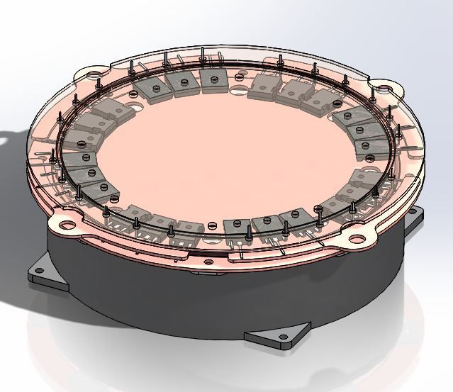
There are two "plates" connected to the capacitor. The lower plate is the high side bus. The upper plate, (it is partially visible in this pic) is the low side bus.
I was able to fit 6 TO-247's per phase leg. 3 high side/3 low side. Each group of 6 switches is tied together with an "output sector" This is that middle copper piece with the big hole in it.
Note that there is actually room for 3 phases and 6 more switches of a boost converter.
Each switch's leg is bent up and goes through a hole in the low side plate. They could all be directly soldered to a round circuit board.

I haven't drawn it yet, but cooling could be down with oil flow between the plates.
Not that you'd
have to have all these switches, it just illustrates the mechanical potential of this design. Of course it would need to be balanced with capacitance, etc. If those SiC switches were used, then it would only need 4 per phase leg to supply the current I need for my project. I also don't know if the motor control capacitor can be shared with the boost converter.
- E*clipse