 10-15-2015, 02:24 PM
|
#2191 (permalink)
|
|
Somewhat crazed
Join Date: Sep 2013
Location: 1826 miles WSW of Normal
Posts: 4,574
Thanks: 597
Thanked 1,258 Times in 1,109 Posts
|
Yes but note 160 a @50% duty. I'll bet the rating includes water cooling because them leads don't calculate big enough for more than 1500 watts switched.
Not trying to a nervous Norvis, but........
__________________
casual notes from the underground:There are some "experts" out there that in reality don't have a clue as to what they are doing.
|
|
|

|
|
The Following User Says Thank You to Piotrsko For This Useful Post:
|
|
 Today Today
|
|
|
|
 Other popular topics in this forum...
|
|
|
|
|
10-15-2015, 02:50 PM
|
#2192 (permalink)
|
|
Permanent Apprentice
Join Date: Jul 2010
Location: norcal oosae
Posts: 523
Thanks: 351
Thanked 318 Times in 215 Posts
|
Quote:
Originally Posted by MPaulHolmes

Notice that the power board is designed for 3 separate phases, with 2 IGBTs (to form a half bridge) per phase, plus 4 IGBTs for the boosting section. That way you could boost, say, 150 amps (shared between 2 IGBTs) at 150v up to 75amps at 300volts. Then the 300volt section would be happy with 1 IGBT, and the low voltage section would be happy with the 150amps shared between 2 IGBTs. Then, to minimize the stray inductance, the driver board mounts perpendicularly to the power board, and the IGBT legs get soldered directly to the driver board. So, the driver board is designed to fit exactly with the footprints of the to-247 IGBTs. The IGBTs get clamped against the base plate with the mounting hardware accessible, "south" of the power board. The legs get bent at a 90 degree angle, and go through the power board, stick through and get soldered to the driver board. It should work OK with 247C and 247D length legs.
Also, notice that the power board accepts either 16 film caps or 8 film caps and 8 electrolytic caps. Exclusive use of film caps would allow for switching at maybe 700v.
Also, notice that 2 of the current sensors are on the power board. There's a new type of current sensor that goes up to 100amp, and is only $8 each, and has a response time of like 1uS. So, 2 of the phases are monitored cheaply (and that's all you need). An external sensor would be needed for the boost section for hardware overcurrent protection. To keep things small, you have to solder the 6 gauge or whatever cable to the surface of phase 2, and to the boost section.
Doing it this way makes the size about 12.35" x 3.6" x 3.6" or so, so it's pretty small and not much wasted space. The down side is it's very much not flexible, but there is no wiring and twisting wires to the power section. The nice thing is, it's really cheap, about as cheap as I can make it.
I could have the 2 microcontrollers speak if I doubled up on the PGC and PGD, which means adding a switch after it is programmed. But then that means possibly changing the pins of the debugger (you have 3 choices for the 2 debugging pins). I could then do the throttle & brake & temperature & temperature2, & voltage on the dspic2010, but would have to send the data to the other one. That means adding voltage monitoring, which adds around $15 or so cost, which isn't bad. There's room on the control board.
The control board is going to be cheap to make, so I could make the other changes later too. I was just trying to do "good enough" for as cheap as possible, without too much extra complexity. I guess I started worrying about messing with PGC and PGD and debugging and sending the important things like throttle so that the dspic4011 then had 2 separate UART conversations going at the same time (uart1 and uart2).
|
Very cool. 
If you're boosting the voltage, don't you have to measure bus voltage at some point? It would seem to be a necessary part of the whole thing. Also, I was hoping to use some of the BMS information for these things. Yes, there will be a voltage drop, but we're talking a few volts vs 650V.
I really like the **ability** to make a 2 layer board. It would be really easy to add a shield if noise is an issue.
I really like everything about this, but I would like to change the capacitor - maybe in a "high performance" version.
I've been warming up to the idea of those smaller package switches. How about this for an idea for a "performance" version:
- Base it on those big cylindrical capacitors.
- The app notes for the caps talk about using sheets of thin metal sheets rather than thick bars to transmit the electricity. By making them parallel and close together, the inductance is dramatically dropped. I've been trying to figure out how to really do this. The suggestions in the app notes are ok, BUT
- Use lots of little TO-247's to pull this off, instead of big IGBT's:
- The high side and low side bus sheets are round disks. The TO247's are attached to the top of one disk and the bottom of the other disk in a circular arrangement with the legs facing radially out. (high side and low side) Using isolated TO247's would allow the switches to be connected directly to their corresponding plates. The control leg would be bent up ( through holes in the plates ) to connect directly to the control board.
- between the plates is a piece of insulating plastic that has channels for cooling oil! The bus plates would also be the cooling system! This would also solve the problem of cooling the bus bars and cooling the capacitor.
Yes there are some assembly issues. Perhaps these could be worked out - like soldering the whole mess in a toaster oven??
Thoughts?
- E*clipse |
|
|
|
|
The Following User Says Thank You to e*clipse For This Useful Post:
|
|
|
10-15-2015, 02:51 PM
|
#2193 (permalink)
|
|
PaulH
Join Date: Feb 2008
Location: Maricopa, AZ (sort of. Actually outside of town)
Posts: 3,832
Thanks: 1,362
Thanked 1,202 Times in 765 Posts
|
I think anything above 100amp each at 50% duty for short periods of time would be a terrible idea. I think the leg limit is around 150amp, but I bet it starts to melt at that current.
|
|
|
|
|
The Following User Says Thank You to MPaulHolmes For This Useful Post:
|
|
|
10-15-2015, 03:31 PM
|
#2194 (permalink)
|
|
Permanent Apprentice
Join Date: Jul 2010
Location: norcal oosae
Posts: 523
Thanks: 351
Thanked 318 Times in 215 Posts
|
Quote:
Originally Posted by MPaulHolmes
I think anything above 100amp each at 50% duty for short periods of time would be a terrible idea. I think the leg limit is around 150amp, but I bet it starts to melt at that current.
|
I was wondering about that - thanks! 
How 'bout this - on the concept I just described, Imagine that the TO247's are located between the sheets, in that space with the insulator & coolant. The TO247's would have cooling oil swirling around them, which would probably cool the legs significantly. 
- E*clipse |
|
|
|
|
10-15-2015, 04:33 PM
|
#2195 (permalink)
|
|
PaulH
Join Date: Feb 2008
Location: Maricopa, AZ (sort of. Actually outside of town)
Posts: 3,832
Thanks: 1,362
Thanked 1,202 Times in 765 Posts
|
You know, I think you are right about having to monitor bus voltage. I was hoping to just have a fixed duty, but you need to be able to change it on the fly based on the output load. The duty would have to go to zero when motor wasn't using any power, otherwise you are boosting into an open circuit which blasts the crap out of your IGBTs.
Fortunately, I changed it all last night haha. But now that I know it's necessary, I feel a lot better. I'll have to reread what you wrote about the layout later. Right now I'm making BOMs for my job. I'm getting the chance to work with SiC mosfets, and hard switching up to maybe 500KHz!!
|
|
|
|
|
The Following User Says Thank You to MPaulHolmes For This Useful Post:
|
|
|
10-15-2015, 07:50 PM
|
#2196 (permalink)
|
|
PaulH
Join Date: Feb 2008
Location: Maricopa, AZ (sort of. Actually outside of town)
Posts: 3,832
Thanks: 1,362
Thanked 1,202 Times in 765 Posts
|
ok now I get what you are saying. That sounds awesome. The symmetry sounds perfect.
|
|
|
|
|
The Following User Says Thank You to MPaulHolmes For This Useful Post:
|
|
|
10-15-2015, 10:21 PM
|
#2197 (permalink)
|
|
Permanent Apprentice
Join Date: Jul 2010
Location: norcal oosae
Posts: 523
Thanks: 351
Thanked 318 Times in 215 Posts
|
Quote:
Originally Posted by MPaulHolmes
ok now I get what you are saying. That sounds awesome. The symmetry sounds perfect.
|
cool!
I'll see if I can throw a solid model of it together. It's really easy to change stuff with SolidWorks, and maybe we can evolve something good.
- E*clipse |
|
|
|
|
10-16-2015, 08:30 PM
|
#2198 (permalink)
|
|
Permanent Apprentice
Join Date: Jul 2010
Location: norcal oosae
Posts: 523
Thanks: 351
Thanked 318 Times in 215 Posts
|
Ok, here's what I was talking about :
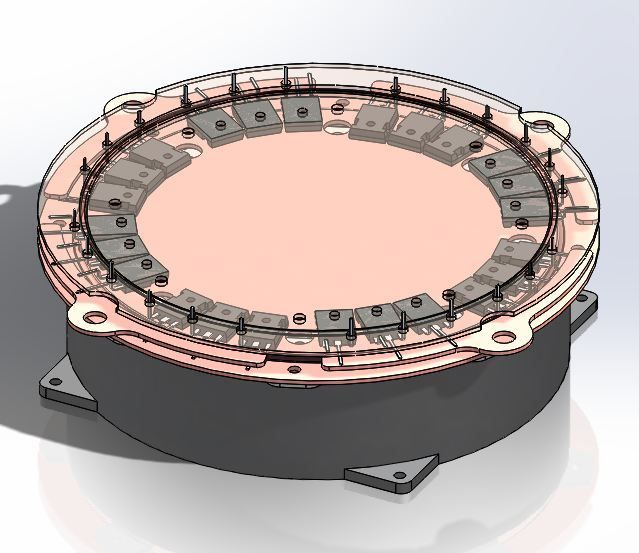
There are two "plates" connected to the capacitor. The lower plate is the high side bus. The upper plate, (it is partially visible in this pic) is the low side bus.
I was able to fit 6 TO-247's per phase leg. 3 high side/3 low side. Each group of 6 switches is tied together with an "output sector" This is that middle copper piece with the big hole in it.
Note that there is actually room for 3 phases and 6 more switches of a boost converter.
Each switch's leg is bent up and goes through a hole in the low side plate. They could all be directly soldered to a round circuit board.
I haven't drawn it yet, but cooling could be down with oil flow between the plates.
Not that you'd have to have all these switches, it just illustrates the mechanical potential of this design. Of course it would need to be balanced with capacitance, etc. If those SiC switches were used, then it would only need 4 per phase leg to supply the current I need for my project. I also don't know if the motor control capacitor can be shared with the boost converter.
- E*clipse |
|
|
|
|
The Following 5 Users Say Thank You to e*clipse For This Useful Post:
|
|
|
10-16-2015, 08:56 PM
|
#2199 (permalink)
|
|
PaulH
Join Date: Feb 2008
Location: Maricopa, AZ (sort of. Actually outside of town)
Posts: 3,832
Thanks: 1,362
Thanked 1,202 Times in 765 Posts
|
You can use the same capacitor for the boost section. Think of the boost as just a 4th phase. Hooked up identically as the other 3 phases. But instead of going to a motor lead, it goes to the boost inductor.
That is beautiful, by the way!!
|
|
|
|
|
The Following 3 Users Say Thank You to MPaulHolmes For This Useful Post:
|
|
|
10-16-2015, 10:10 PM
|
#2200 (permalink)
|
|
Permanent Apprentice
Join Date: Jul 2010
Location: norcal oosae
Posts: 523
Thanks: 351
Thanked 318 Times in 215 Posts
|
Quote:
Originally Posted by MPaulHolmes
You can use the same capacitor for the boost section. Think of the boost as just a 4th phase. Hooked up identically as the other 3 phases. But instead of going to a motor lead, it goes to the boost inductor.
That is beautiful, by the way!!
|
Thank you! It's one of those waking thoughts that worked itself out... I guess if you're nutty enough to be thinking about this all the time, perhaps some inspiration will come along...
That's great news about sharing the capacitor. Then a serious question I still haven't found a good answer for - maybe you have: How much capacitance will work? In this case the inductance would be ridiculously low. In fact, those "plates" are sort of a capacitor. Do you have a definitive source for some equations on this?
Those boost switches would probably need to carry more current than a phase leg. For example, if the battery voltage is 1/2X, the boost switches need to carry 2X, right?
Oh yea - there is the issue of measuring phase current. I guess it would be possible to use a sensor around the output leads. Do you have a cleaner suggestion? Maybe those little hall effect sensors on 1/2 of each output??
And on assembly - this would require soldering big pieces of copper. As far as I can tell, it would need to be all done at once. Any suggestions would be extremely helpful..
|
|
|
|
|


