My boost/AC board is done. I was able to add the SOIC8 melexis current sensor to the other side of the power board, and then just solder a small piece of 8 gauge solid copper right above (to carry the heavy current right above the sensor). That way you can monitor currents up to whatever level you want, and each current sense circuit only costs like $4 in quantity 1. So, the cost in quantity one of a person ordering everything is about $350 from Mouser. $120 of that is 5 big 110uF 500v film caps and maybe $80 of it is 10 of the big bertha 160amp continuous "TO-247 super" IGBTs. I'm hoping 100amp for short periods will be OK (per phase).
I had to abandon the ALPS solder in current sensor because it was rated for 50amp continuous, and 100amp peak (and 110amp absolute max). Plus, it was $11.
There's a neat new inductor that's rated for 100amp continuous, 150amp for short periods of time that's 120uHenry and $144. Allied Electronics says the shipping weight is 9 pounds, which isn't too bad. I don't think the 10uH 200amp inductor would work in this application based on the simulations I ran.
I've just about got the control scheme down for the boosting. The whole transition from discontinuous to continuous mode is fascinating to watch. Here's the control plan:
An AC motor, as far as I know, runs exactly the same on 12vDC or 500vDC until Vd and Vq hit the boundary of the voltage disk. So, you always try to have the boost be 0% duty. Each time you crash into the boundary (where the field weakening starts), boost up a small step. This sudden boost increase looks like this:
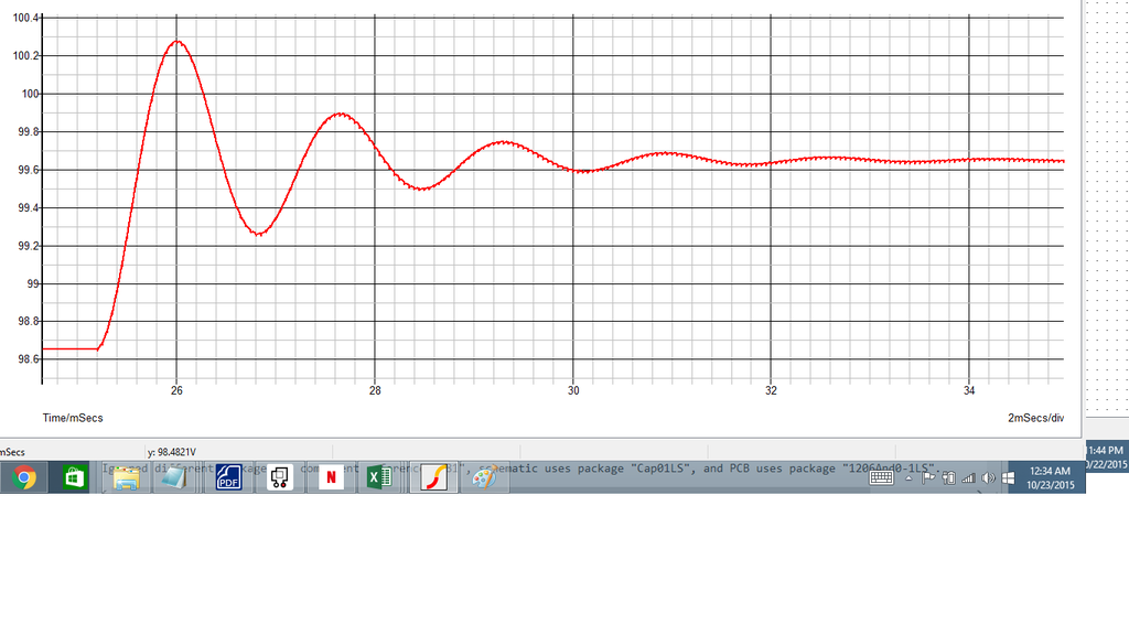
So, you don't want to have too big of a step in boosting. If the bus capacitors are at a low voltage, a big boosting step means you are dumping TONS of current into the caps, which will trip the hardware overcurrent probably. And, you want to give it some time for the ringing to stop. So, boost, say, 1% and then wait 0.01sec for the ringing to stop.
Going from lots of boosting to zero boosting doesn't have the problem of dumping into an empty capacitor. The motor just uses the voltage in the caps until the voltage is reduced to the point that the field weakening starts again. At that point you slowly boost up again until it stops. The trouble is, how do you quickly go from 0 boosting to stopping the field weakening without dumping into the caps causing a hardware overcurrent trip? I'm thinking that if you set the duty to a little lower than the required duty to cause Vin * 1/(1-duty) = vOut, where Vout is the actual known bus voltage (found from voltage monitoring), you could step to that boosting level, and then gradually increase from there. That should avoid the "dumping into empty caps" phenomenon.
Then, you just update the PI loop values each cycle based on the current voltage level (which is being monitored now). The higher the voltage, the smaller the Kp and Ki.