 10-22-2015, 01:01 AM
|
#2221 (permalink)
|
|
PaulH
Join Date: Feb 2008
Location: Maricopa, AZ (sort of. Actually outside of town)
Posts: 3,832
Thanks: 1,362
Thanked 1,202 Times in 765 Posts
|
I could try hooking up my 200amp 300uH inductor between the batteries and the capacitor, then hook up the oscilloscope on B+ and B- on the capacitor (so current spikes can't be pulled from the batteries, only smoothness comes from them). Then, from the voltage spike drop or whatever, and the 100uOhm advertised resistance, maybe we can infer the ripple current?
|
|
|

|
 Today Today
|
|
|
|
 Other popular topics in this forum...
|
|
|
|
|
10-22-2015, 03:50 AM
|
#2222 (permalink)
|
|
Permanent Apprentice
Join Date: Jul 2010
Location: norcal oosae
Posts: 523
Thanks: 351
Thanked 318 Times in 215 Posts
|
Honestly, Paul, I wouldn't go to that trouble. 
I think that between what SBE shows on their various tests and what I've seen on my simulation, the specifics are very important. IMHO, Doing a test with a different inductance, resistance and bus connection system would be too much variation.
I think the motor inductance has a very strong relation to the ripple current, for example. Other factors like bus impedance and switch "on" resistance also had big affects on the ripple current.
I did get through to someone at SBE who was a little more willing to help. I asked him for at least some rough parameters that would allow me to see if my model was reasonably accurate. Here's the reply; it's good to see that the model is working! 
Quote:
The ripple current usually equal to 60% current rated. Base on ripple current number to decide how big capacitance you need..
But the ripple voltage will be too high if the capacitance is too low. So you should decide whats the capacitance your system minimum needed.
Thanks,
Wayne Liu
SBE
|
Paul - have you been able to check out these capacitors with respect to the turn-off voltage spike? A while ago I though you said that someone @ SBE said a capacitor rated for 700V would be adequate. Or maybe I'm remembering something else? |
|
|
|
|
10-22-2015, 09:15 AM
|
#2223 (permalink)
|
|
PaulH
Join Date: Feb 2008
Location: Maricopa, AZ (sort of. Actually outside of town)
Posts: 3,832
Thanks: 1,362
Thanked 1,202 Times in 765 Posts
|
I think I did that test of the turn-off spike, but now I don't remember the results. I could do it again. I know the "theoretical" turnoff spike is supposed to be:
V_turnoff_spike = L * di/dt. And the sbe ring cap is supposed to have about 5nH of stray inductance "in a suitable laminar bus structure" haha. So, if you are turning off in 1uS:
V_turnoff_spike = 5*10^-9 * 1000Amp/10^-6
= 5 volts, assuming 1000amp.
|
|
|
|
|
The Following User Says Thank You to MPaulHolmes For This Useful Post:
|
|
|
10-22-2015, 02:59 PM
|
#2224 (permalink)
|
|
Permanent Apprentice
Join Date: Jul 2010
Location: norcal oosae
Posts: 523
Thanks: 351
Thanked 318 Times in 215 Posts
|
Quote:
Originally Posted by MPaulHolmes

I think I did that test of the turn-off spike, but now I don't remember the results. I could do it again. I know the "theoretical" turnoff spike is supposed to be:
V_turnoff_spike = L * di/dt. And the sbe ring cap is supposed to have about 5nH of stray inductance "in a suitable laminar bus structure" haha. So, if you are turning off in 1uS:
V_turnoff_spike = 5*10^-9 * 1000Amp/10^-6
= 5 volts, assuming 1000amp.
|
That's good news; great - in fact.
Just roughly speaking - no solid numbers - did the tests you did sort of match the theory?
So, lets say I really screw up the bus design and the inductance is thee times that. At the same time, my insanity w/ SiC drives me to decrease the turn off time to 28nS driving the Wolfspeed SiC switch as hard as possible. Fortunately, I'm running about 200A max (1/5 of the estimate).
With all that silliness:
V_turnoff_spike = 15*10^-9*200Amp/28^-9 = 107V
That sounds bad, except 200A is twice the current I will use AND I'm not likely to screw up the bus structure that bad. The main parameter I can screw up in the bus structure is the distance between the plates, and that's not a very sensitive number.
So, it sounds like a 700V max capacitor would be pushing the limits, but work. It seems there's a decent safety overkill in those capacitors. For example the 700V rated capacitor can handle 950V for two minutes. A 900V capacitor would be really safe. That's great news- there's lots of choice in the 8 1/2" diameter range - up to 1000uF.
Thanks a bunch!
- E*clipse |
|
|
|
|
10-22-2015, 07:44 PM
|
#2225 (permalink)
|
|
Permanent Apprentice
Join Date: Jul 2010
Location: norcal oosae
Posts: 523
Thanks: 351
Thanked 318 Times in 215 Posts
|
Quick question when wiring multiple small switches, like the TO-247:
If all the switches in question are connected to a common high or low side and a common output, can you just gang all the gate pins and use a common resistance?
Or would it be better to run an individual resistor to each one?
Is the ability to run them in parallel connected to the gate resistance?
Thank a bunch,
E*clipse
|
|
|
|
|
10-22-2015, 07:45 PM
|
#2226 (permalink)
|
|
PaulH
Join Date: Feb 2008
Location: Maricopa, AZ (sort of. Actually outside of town)
Posts: 3,832
Thanks: 1,362
Thanked 1,202 Times in 765 Posts
|
absolutely positively essentially necessarily use separate gate resistors.
|
|
|
|
|
The Following 2 Users Say Thank You to MPaulHolmes For This Useful Post:
|
|
|
10-22-2015, 11:04 PM
|
#2227 (permalink)
|
|
Master EcoModder
Join Date: Sep 2010
Location: Saskatoon, canada
Posts: 1,488
Thanks: 746
Thanked 565 Times in 447 Posts
|
Quote:
Originally Posted by MPaulHolmes
absolutely positively essentially necessarily use separate gate resistors.
|
Are you sure Paul? You seem to be a bit INDECISIVE about this topic  |
|
|
|
|
The Following User Says Thank You to thingstodo For This Useful Post:
|
|
|
10-23-2015, 03:44 AM
|
#2228 (permalink)
|
|
PaulH
Join Date: Feb 2008
Location: Maricopa, AZ (sort of. Actually outside of town)
Posts: 3,832
Thanks: 1,362
Thanked 1,202 Times in 765 Posts
|
My boost/AC board is done. I was able to add the SOIC8 melexis current sensor to the other side of the power board, and then just solder a small piece of 8 gauge solid copper right above (to carry the heavy current right above the sensor). That way you can monitor currents up to whatever level you want, and each current sense circuit only costs like $4 in quantity 1. So, the cost in quantity one of a person ordering everything is about $350 from Mouser. $120 of that is 5 big 110uF 500v film caps and maybe $80 of it is 10 of the big bertha 160amp continuous "TO-247 super" IGBTs. I'm hoping 100amp for short periods will be OK (per phase).
I had to abandon the ALPS solder in current sensor because it was rated for 50amp continuous, and 100amp peak (and 110amp absolute max). Plus, it was $11.
There's a neat new inductor that's rated for 100amp continuous, 150amp for short periods of time that's 120uHenry and $144. Allied Electronics says the shipping weight is 9 pounds, which isn't too bad. I don't think the 10uH 200amp inductor would work in this application based on the simulations I ran.
I've just about got the control scheme down for the boosting. The whole transition from discontinuous to continuous mode is fascinating to watch. Here's the control plan:
An AC motor, as far as I know, runs exactly the same on 12vDC or 500vDC until Vd and Vq hit the boundary of the voltage disk. So, you always try to have the boost be 0% duty. Each time you crash into the boundary (where the field weakening starts), boost up a small step. This sudden boost increase looks like this:
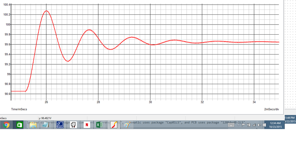
So, you don't want to have too big of a step in boosting. If the bus capacitors are at a low voltage, a big boosting step means you are dumping TONS of current into the caps, which will trip the hardware overcurrent probably. And, you want to give it some time for the ringing to stop. So, boost, say, 1% and then wait 0.01sec for the ringing to stop.
Going from lots of boosting to zero boosting doesn't have the problem of dumping into an empty capacitor. The motor just uses the voltage in the caps until the voltage is reduced to the point that the field weakening starts again. At that point you slowly boost up again until it stops. The trouble is, how do you quickly go from 0 boosting to stopping the field weakening without dumping into the caps causing a hardware overcurrent trip? I'm thinking that if you set the duty to a little lower than the required duty to cause Vin * 1/(1-duty) = vOut, where Vout is the actual known bus voltage (found from voltage monitoring), you could step to that boosting level, and then gradually increase from there. That should avoid the "dumping into empty caps" phenomenon.
Then, you just update the PI loop values each cycle based on the current voltage level (which is being monitored now). The higher the voltage, the smaller the Kp and Ki.
Last edited by MPaulHolmes; 10-23-2015 at 11:58 AM..
|
|
|
|
|
The Following 2 Users Say Thank You to MPaulHolmes For This Useful Post:
|
|
|
10-23-2015, 07:57 PM
|
#2229 (permalink)
|
|
Permanent Apprentice
Join Date: Jul 2010
Location: norcal oosae
Posts: 523
Thanks: 351
Thanked 318 Times in 215 Posts
|
That sounds awesome Paul!
Being able to adjust it according to motor operating parameters would also give you options for optimizing motor efficiency. If you don't boost as high, you won't have to buck as much on the inverter side.
You can kind of see this in operation with the Prius tests @ ORNL. They did a range of tests with the bus voltage at 250V, 500V, and 650V.
Nice Work!!
- E*clipse |
|
|
|
|
The Following User Says Thank You to e*clipse For This Useful Post:
|
|
|
10-23-2015, 08:10 PM
|
#2230 (permalink)
|
|
PaulH
Join Date: Feb 2008
Location: Maricopa, AZ (sort of. Actually outside of town)
Posts: 3,832
Thanks: 1,362
Thanked 1,202 Times in 765 Posts
|
I think I"m going to have 2 separate power boards. One with electrolytic caps, and one with dc link film caps. You can fit 12 of 60uF film caps, for a total ripple rating of about 200amp. But the cost is about $160. You can also do 15 of 470uF 400v electrolytic caps that have similar characteristics to the ones I use in the 500amp DC controller (so I know it would be good enough). That would also make the DC bus change much more slowly from the boosting and bucking (millisec instead of microsec) so you wouldn't have to be quite as vigilant in the software. And then you can also do it for $59. So, then the cost of parts would be $290 (in quantity 1) or so. Well, you would need an extra current sensor, dang it. I can only fit 2 on the power board.The 3000hour rating isn't such a big deal. That's like 1 hour of driving daily for 9 years.
|
|
|
|
|
The Following User Says Thank You to MPaulHolmes For This Useful Post:
|
|
|


